Product overview
C9900-G05x12 Version: 1.0
3.2 Interface description
The following interface is provided for controlling the push-button extension:
• Signal and power supply (XS01)
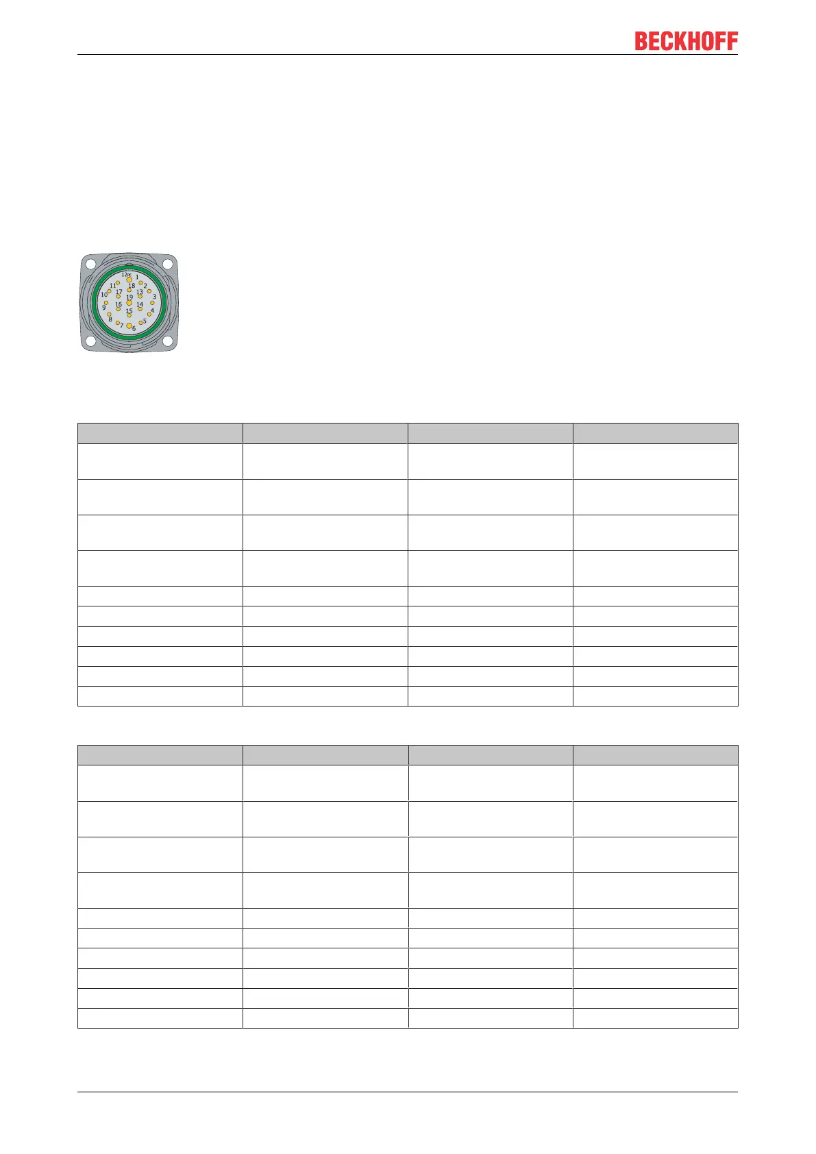
Signal and power supply (XS01)
The C9900-G05x push-button extensions are supplied with a nominal input voltage of 24 V, which may
actually lie between 20.4 and 28.8 V. The power supply is connected to pin 19 of the 19-pin round connector
(XS01). GND is on pin 6.
Fig.2: C9900-G05x Signal and Power Supply
Table3: C9900-G050 and C9900-G052 pin assignment
Pin Signal Pin Signal
1 Emergency stop S1 input
break contact 1
11 S4 output make contact
2 Emergency stop S1
output break contact 1
12 PE
3 Emergency stop S1 input
break contact 2
13 reserve
4 Emergency stop S1
output break contact 2
14 reserve
5 S2 input make contact 15 reserve
6 GND 16 reserve
7 S2 output make contact 17 reserve
8 S3 input break contact 18 reserve
9 S3 output break contact 19 + 24V
10 S4 input make contact
Table4: C9900-G054 and C9900-G056 pin assignment
Pin Signal Pin Signal
1 Emergency stop S1 input
break contact 1
11 S4 output make contact
2 Emergency stop S1
output break contact 1
12 PE
3 Emergency stop S1 input
break contact 2
13 S5 input make contact
4 Emergency stop S1
output break contact 2
14 S5 output make contact
5 S2 input make contact 15 reserve
6 GND 16 reserve
7 S2 output make contact 17 reserve
8 S3 input break contact 18 reserve
9 S3 output break contact 19 + 24V
10 S4 input make contact

 Loading...