Product overview
C9900-G05x18 Version: 1.0
Table11: Assignment of connection strip - A972 three-button board
Connection strip Terminal point Description
1 1 24 V DC
2 0 V
2 1 Input break contact 2.1
2 Output break contact 2.1
3 Output break contact 2.2
4 Input break contact 2.2
5 Input make contact 3.1
6 Output make contact 3.1
7 Output make contact 3.2
8 Input make contact 3.2
3 1 LED1
2 LED2
3 LED3
4 Not used
5 Input make contact 1.1
6 Output make contact 1.1
7 Output make contact 1.2
8 Input make contact 1.2
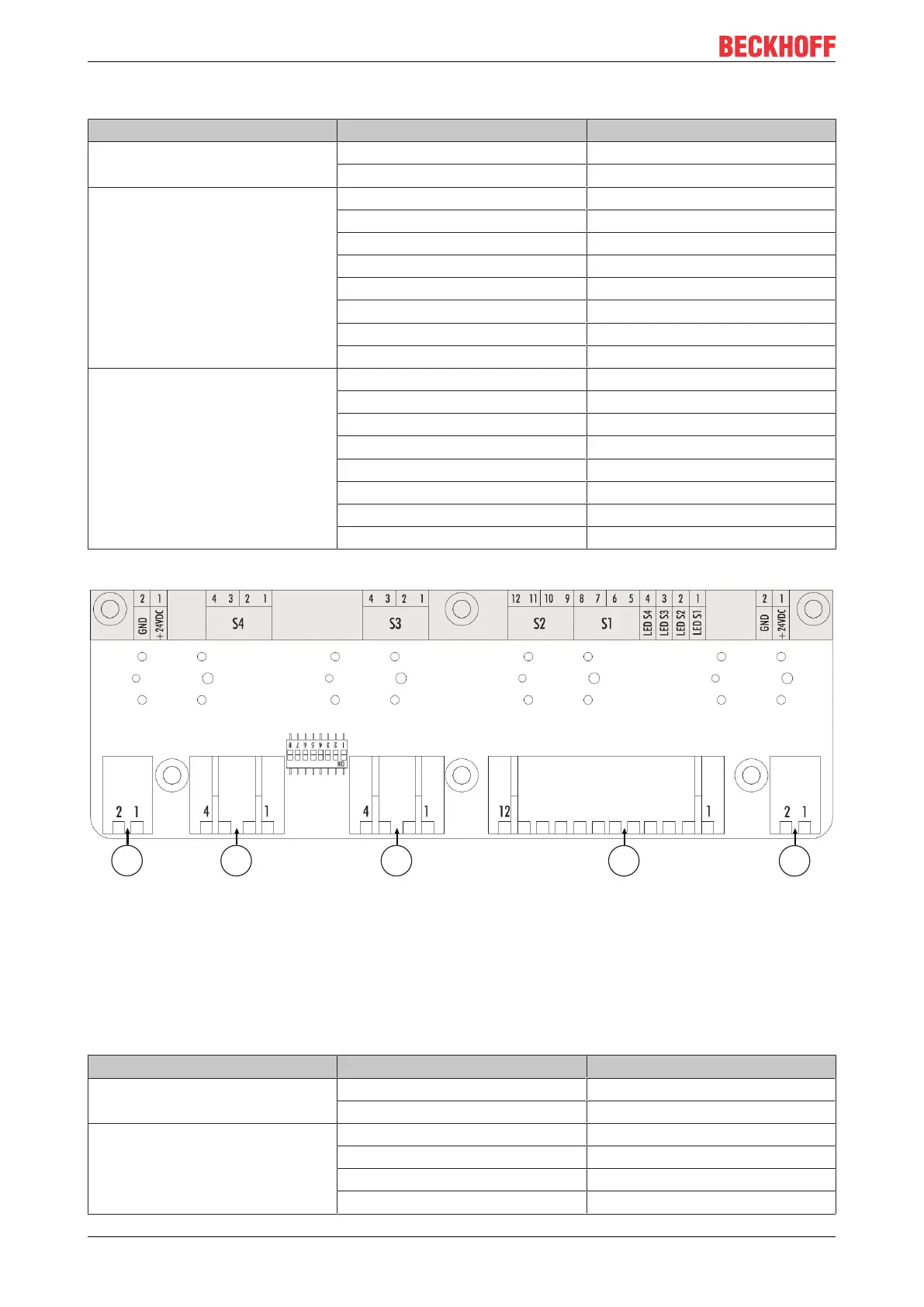
4-button board for C9900-G055 and C9900-G057
Fig.8: A973 4-button board
The 4-button board has two external connection strips 1, CON600 & CON601, which are used for the power
supply to the board. LEDs 1-4 and the push-buttons S1 and S2 are wired via connection strip 4, CON602.
Connection strip 2, CON603, is used for the wiring of the push-button S3. Connection strip 2, CON604, is
used for the wiring of the push-button S4.
Table12: Assignment of connection strip - A974 four-button board
Connection strip Terminal point Description
1 1 24 V DC
2 0 V
2 1 Input make contact 4.1
2 Output make contact 4.1
3 Output make contact 4.2
4 Input make contact 4.2

 Loading...