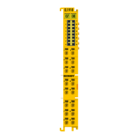
Product overview
EL70x118 Version: 4.4
2.2 EL7031 - Technical data
Technical data EL7031
Number of outputs 1 stepper motor, 2 phases
Power supply for output stage (via power contacts) 24V
DC
(-15% / +20%)
Non-reactive outputs
yes (see notice [}15])
Number of inputs 2
Supply voltage 24V
DC
via the power contacts, via the E-bus
Output current 1.5 A (overload- and short-circuit-proof)
Maximum step frequency 1000, 2000, 4000 or 8000 full steps/s (configurable)
Step pattern full step, half step, up to 64-fold micro stepping
Current controller frequency approx. 25 kHz
Input signal voltage "0" -3V … 2V
Input signal voltage "1" 2.5V … 28V
Input current typ. 5mA
Diagnostic LED error phase A and B, loss of step/stagnation, power, enable
Resolution approx. 5,000 positions in typical applications (per revolution)
Power supply via the E-bus, encoder/driver stage/motor: via the power contacts
Current consumption via E-bus typ. 120 mA
Electrical isolation 500 V (E-bus/signal voltage)
Supports NoCoeStorage [}32] function
from firmware 04
Configuration no address setting required
configuration via TwinCAT System Manager
Weight approx. 105 g
Permissible ambient temperature range during operation 0°C ... + 55°C
Permissible ambient temperature range during storage -25°C ... + 85°C
Permissible relative humidity 95%, no condensation
Dimensions (W x H x D) approx. 15 mm x 100 mm x 70 mm (width aligned: 12 mm)
Mounting [}38]
on 35 mm mounting rail conforms to EN 60715
Vibration/shock resistance conforms to EN 60068-2-6 / EN 60068-2-27,
see also installation instructions [}40] for enhanced mechanical
load capacity
EMC immunity/emission conforms to EN 61000-6-2 / EN 61000-6-4
according to IEC/EN 61800-3
EMC category Category C3 - standard
Category C2, C1 - auxiliary filter required
Protection class IP20
Installation position
without fan cartridge ZB8610: standard installing position
with fan cartridge ZB8610: standard installing position, other installing
positions (example 1 & 2)
see notice [}45]
Approval CE
cULus [}49]
 Loading...