Operation
EP1957-0022 and EP1957-2222 25Version: 2.0.0
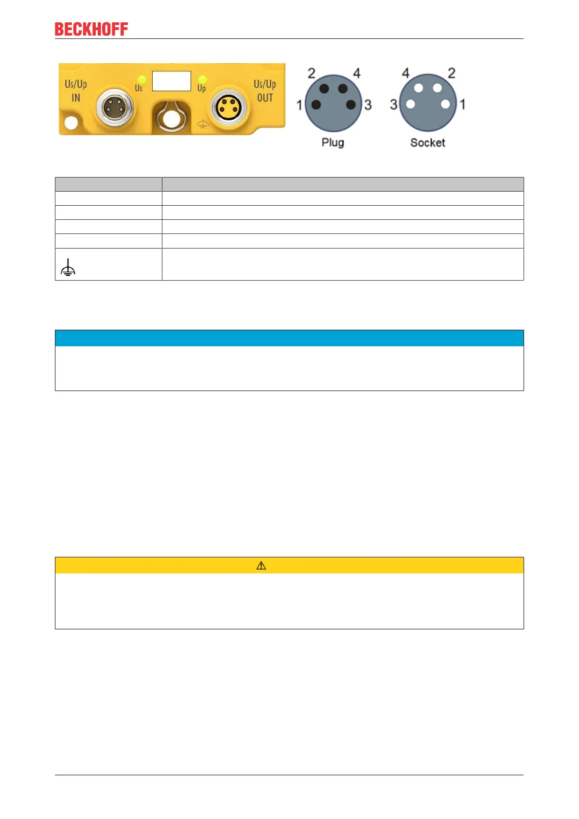
Power connection
M8 - pin assignment
Contact Voltage
1 Control voltage Us, +24V
DC
2 Peripheral voltage Up, +24V
DC
3 GND Us
4 GND Up
Connecting the functional earth
The contacts of the M8 connectors can conduct a maximum current of 4A.
Two LEDs indicate the status of the supply voltages.
NOTE
Do not confuse the power port with EtherCAT port!
Never connect the power cables (M8, 24V
DC
) to the green-marked EtherCAT sockets of the EtherCAT Box
modules. This can cause the destruction of the modules!
Control voltage Us
The fieldbus and the processor logic are supplied from the 24V
DC
control voltage Us. The control voltage is
electrically isolated from the fieldbus circuitry.
Peripheral voltage Up
The peripheral voltage Up supplies the digital clock outputs, the safe inputs and the safe outputs.
Redirection of the supply voltages
The power IN and OUT connections are bridged in the module. Hence, the supply voltages Us and Up can
be passed from EtherCATBox to EtherCATBox in a simple manner.
CAUTION
Note the maximum current!
For the distribution of the supply voltages Us and Up, please note that the maximum permitted current of
4A for the respective contacts of the M8 plug connector should not be exceeded, even in the event of a
fault, e.g. short circuit!
 Loading...