List of figures
EP1957-0022 and EP1957-2222 57Version: 2.0.0
List of figures
Fig. 1 EtherCAT Box modules extend the EtherCAT system with IP67 protection................................ 14
Fig. 2 Connection diagram..................................................................................................................... 15
Fig. 3 Dimensions .................................................................................................................................. 20
Fig. 4 Mounting rail ZS5300-0001.......................................................................................................... 22
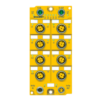
Fig. 5 EtherCAT Box with M8 and M12 connectors ............................................................................... 22
Fig. 6 Torque wrench ZB8801................................................................................................................ 23
Fig. 7 EtherCAT connection 30 mm housing M8 ................................................................................... 23
Fig. 8 Safe inputs 1 to 8 ......................................................................................................................... 26
Fig. 9 PinOut default setting................................................................................................................... 26
Fig. 10 PinOut alternative 1 (parameter input power mode = power mode A)......................................... 26
Fig. 11 PinOut alternative 2 (parameter input power mode = power mode B)......................................... 26
Fig. 12 Characteristic curve of the inputs................................................................................................. 28
Fig. 13 Safe outputs 1 to 4 ....................................................................................................................... 28
Fig. 14 PinOut safe output ....................................................................................................................... 29
Fig. 15 Signal lines................................................................................................................................... 30
Fig. 16 Cable routing................................................................................................................................ 31
Fig. 17 Adding an EP1957 ....................................................................................................................... 32
Fig. 18 EP1957 - Delete project data ....................................................................................................... 33
Fig. 19 Rotary switches on the underside ................................................................................................ 34
Fig. 20 Starting the automatic import from the I/O configuration.............................................................. 35
Fig. 21 Selection from the I/O tree ........................................................................................................... 35
Fig. 22 Creating alias devices by the user ............................................................................................... 36
Fig. 23 Linking tab.................................................................................................................................... 37
Fig. 24 Connection tab ............................................................................................................................. 38
Fig. 25 Safety Parameter tab ................................................................................................................... 39
Fig. 26 Process image ............................................................................................................................. 41
Fig. 27 Typical reaction time .................................................................................................................... 43
Fig. 28 Worst-case reaction time ............................................................................................................. 44
Fig. 29 EtherCAT- Fieldbus LEDs............................................................................................................ 45
Fig. 30 Status LEDs ................................................................................................................................. 46
Fig. 31 Diagnostic LEDs........................................................................................................................... 48
Fig. 32 Serial number............................................................................................................................... 50
Fig. 33 EP1957 EC Declaration of Conformity......................................................................................... 56
 Loading...