Operation
EP1957-0022 and EP1957-2222 27Version: 2.0.0
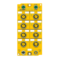
M12 connection
(numbered in red)
Contact Chan-
nel
Signal Alternative 1:
Parameter
PowerMode A
Alternative 2:
Parameter
PowerMode B
1 1 1 Pulse output 1 24V
DC
sensor power supply
0V
DC
sensor power supply
2 Input 1 Input 1 Input 1
3 2 Pulse output 2 0V
DC
sensor power supply
24V
DC
sensor power supply
4 Input 2 Input 2 Input 2
5 - not connected not connected not connected
2 1 3 Pulse output 3 24V
DC
sensor power supply
0V
DC
sensor power supply
2 Input 3 Input 3 Input 3
3 4 Pulse output 4 0V
DC
sensor power supply
24V
DC
sensor power supply
4 Input 4 Input 4 Input 4
5 - not connected not connected not connected
3 1 5 Pulse output 5 24V
DC
sensor power supply
0V
DC
sensor power supply
2 Input 5 Input 5 Input 5
3 6 Pulse output 6 0V
DC
sensor power supply
24V
DC
sensor power supply
4 Input 6 Input 6 Input 6
5 - not connected not connected not connected
4 1 7 Pulse output 7 24V
DC
sensor power supply
0V
DC
sensor power supply
2 Input 7 Input 7 Input 7
3 8 Pulse output 8 0V
DC
sensor power supply
24V
DC
sensor power supply
4 Input 8 Input 8 Input 8
5 - not connected not connected not connected
Sensor power supply
For the sensor supply, please ensure that the maximum current consumption does not exceed
250mA and the parameter Diag TestPulse active is set to FALSE.
CAUTION
Configurable inputs
The inputs 1 to 8 can be occupied as you want with normally closed contacts or normally open contacts.
The corresponding evaluation takes place in the safety controller.
Alternatively, a safe sensor can be supplied with 24V
DC
, instead of the clock outputs for potential-free
contacts. The polarity of pins 1 and 3 can be parameterized. Detection of cross-circuits or external feeds
must take place via the connected safe sensor.
Functional earth
Pin 5 of the M12 connections is not connected to the functional ground, since an SELV/PELV power
supply unit is specified for the EtherCAT Box.
 Loading...