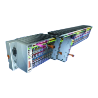
Product overview
KL304x, KL305x12 Version: 4.0
◦ On: The limit stop of the A/D converter has been reached. The current is greater than 21.5mA.
◦ Off: Normal operation
Process data output format
In the delivery state the process data are shown in two's complement form (integer -1 corresponds to
0xFFFF). Other presentation types can be selected via the feature register (R32) [}37] (e.g.signed amount
representation, Siemens output format).
Measured value Output
KL304x KL305x dec hex
0mA 4mA 0 0x0000
10mA 12mA 16383 0x3FFF
20mA 20mA 32767 0x7FFF
Calculation of process data
The terminal continuously takes measured values and stores the raw values of its A/D converter in register
R0 [}35] (RAM ). The calculation of the correction with the calibration values takes place after each
sampling of the analog signal. This is followed by manufacturer and user scaling:
The process data that are transferred to the Bus Coupler are calculated using the following equations:
Y_a = (B_a + X_adc) * A_a
Y_aus = Y_a
(1.0) Neither user nor manufacturer scaling is active.
Y_1 = B_h + A_h * Y_a
Y_aus = Y_1
(1.1) Manufacturer scaling active: (Default setting)
Y_2 = B_w + A_w * Y_a
Y_aus = Y_2
(1.2) User scaling active
Y_1 = B_h + A_h * Y_a
Y_2 = B_w + A_w * Y_1
Y_aus = Y_2
(1.3)
(1.4)
Manufacturer and user scaling active
Key
Name Name Register
X_adc Output value of the A/D converter -
Y_aus Process data for controller -
B_a Vendor calibration: Offset
R17 [}36]
A_a Vendor calibration: Gain
R18 [}36]
B_h Manufacturer scaling: Offset
R19 [}36]
A_h Manufacturer scaling: Gain
R20 [}36]
B_w User scaling: Offset
R33 [}37]
A_w User scaling: Gain
R34 [}37]
The equations of the straight line are enabled via register R32 [}37].
Fig.4: KL304x, KL305x - Data flow
 Loading...