Access from the user program
KL304x, KL305x 29Version: 4.0
5 Access from the user program
5.1 Terminal configuration
The terminal can be configured and parameterized via the internal register structure. Each terminal channel
is mapped in the Bus Coupler. Mapping of the terminal data in the Bus Coupler memory may differ,
depending on the Bus Coupler type and the set mapping configuration (e.g.Motorola/Intel format, word
alignment etc.). For parameterizing a terminal, the control and status byte also has to be mapped.
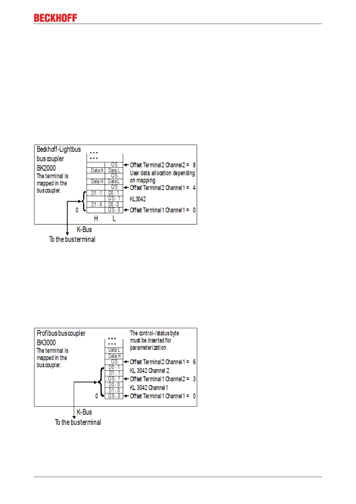
BK2000 Lightbus Coupler
In the BK2000 Lightbus Coupler, the control/status byte is always mapped, in addition to the data bytes. This
is always located in the low byte at the offset address of the terminal channel.
Fig.17: Mapping in the Lightbus coupler - example for KL3042 and KL3052
BK3000 Profibus Coupler
For the BK3000 Profibus coupler, the master configuration should specify for which terminal channels the
control and status byte is to be inserted. If the control and status byte are not evaluated, the terminals
occupy 2bytes per channel:
• KL3041 and KL3051: 2bytes of input data
• KL3042 and KL3052: 4bytes of input data
• KL3044 and KL3054: 8bytes of input data
Fig.18: Mapping in the Profibus coupler - example for KL3042 and KL3052
BK4000 Interbus Coupler
The BK4000 Interbus Coupler maps the terminals in the delivery state with 2bytes per channel:
 Loading...