Mounting and wiring
KL304x, KL305x22 Version: 4.0
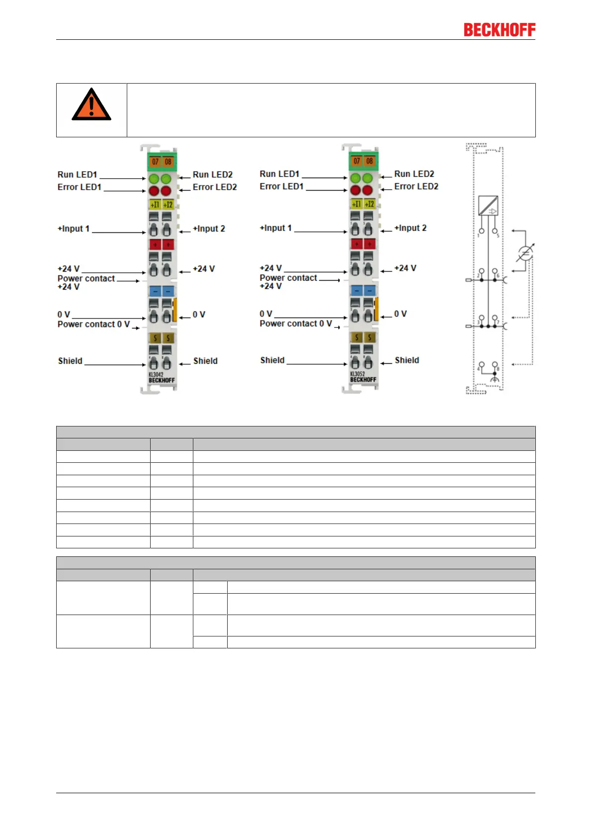
3.6 KL3042, KL3052 - Connection and LED description
WARNING
Risk of injury through electric shock and damage to the device!
Bring the Bus Terminals system into a safe, de-energized state before starting mounting,
disassembly or wiring of the Bus Terminals!
Fig.14: KL3042, KL3052 - Connection and LEDs
Connection of KL3042, KL3052
Terminal point No. Comment
+Input 1 1 + Input 1
+24V 2 +24V (internally connected to terminal point 6 and positive power contact)
0V 3 0V (internally connected to terminal point 7 and negative power contact)
Shield 4 PE contact (internally connected to terminal point 8)
+Input 2 5 + Input 2
+24V 6 +24V (internally connected to terminal point 2 and positive power contact)
0V 7 0V (internally connected to terminal point 3 and negative power contact)
Shield 8 PE contact (internally connected to terminal point 4)
KL3042, KL3052 - LED description
LED Color Description
Run1 LED,
Run2 LED
green On: Normal operation
Off: Watchdog-timer overflow has occurred. If no process data is transmitted to the bus
coupler for 100ms, the green LEDs go out
Error1 LED,
Error2 LED
red On: The limit stop of the A/D converter has been reached. The current is greater than
21.5mA.
Off: Normal operation
 Loading...