List of illustrations
KL304x, KL305x46 Version: 4.0
List of illustrations
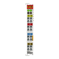
Fig. 1 KL3041, KL3051 .......................................................................................................................... 8
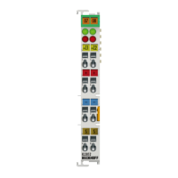
Fig. 2 KL3042, KL3052 .......................................................................................................................... 9
Fig. 3 KL3044, KL3054 .......................................................................................................................... 10
Fig. 4 KL304x, KL305x - Data flow ........................................................................................................ 12
Fig. 5 Spring contacts of the Beckhoff I/O components......................................................................... 13
Fig. 6 Attaching on mounting rail ........................................................................................................... 14
Fig. 7 Disassembling of terminal............................................................................................................ 15
Fig. 8 Power contact on left side............................................................................................................ 16
Fig. 9 Standard wiring............................................................................................................................ 18
Fig. 10 Pluggable wiring .......................................................................................................................... 18
Fig. 11 High Density Terminals................................................................................................................ 18
Fig. 12 Connecting a cable on a terminal point ....................................................................................... 19
Fig. 13 KL3041, KL3051 - Connection and LEDs.................................................................................... 21
Fig. 14 KL3042, KL3052 - Connection and LEDs.................................................................................... 22
Fig. 15 KL3044, KL3054 - Connection and LEDs.................................................................................... 23
Fig. 16 KS2000 configuration software.................................................................................................... 27
Fig. 17 Mapping in the Lightbus coupler - example for KL3042 and KL3052 .......................................... 29
Fig. 18 Mapping in the Profibus coupler - example for KL3042 and KL3052 .......................................... 29
Fig. 19 Mapping in the Interbus coupler - example for KL3042 and KL3052........................................... 30
Fig. 20 Register mode control byte.......................................................................................................... 40
 Loading...