Access from the user program
KL304x, KL305x40 Version: 4.0
5.5.2 Register communication
Register access via process data exchange
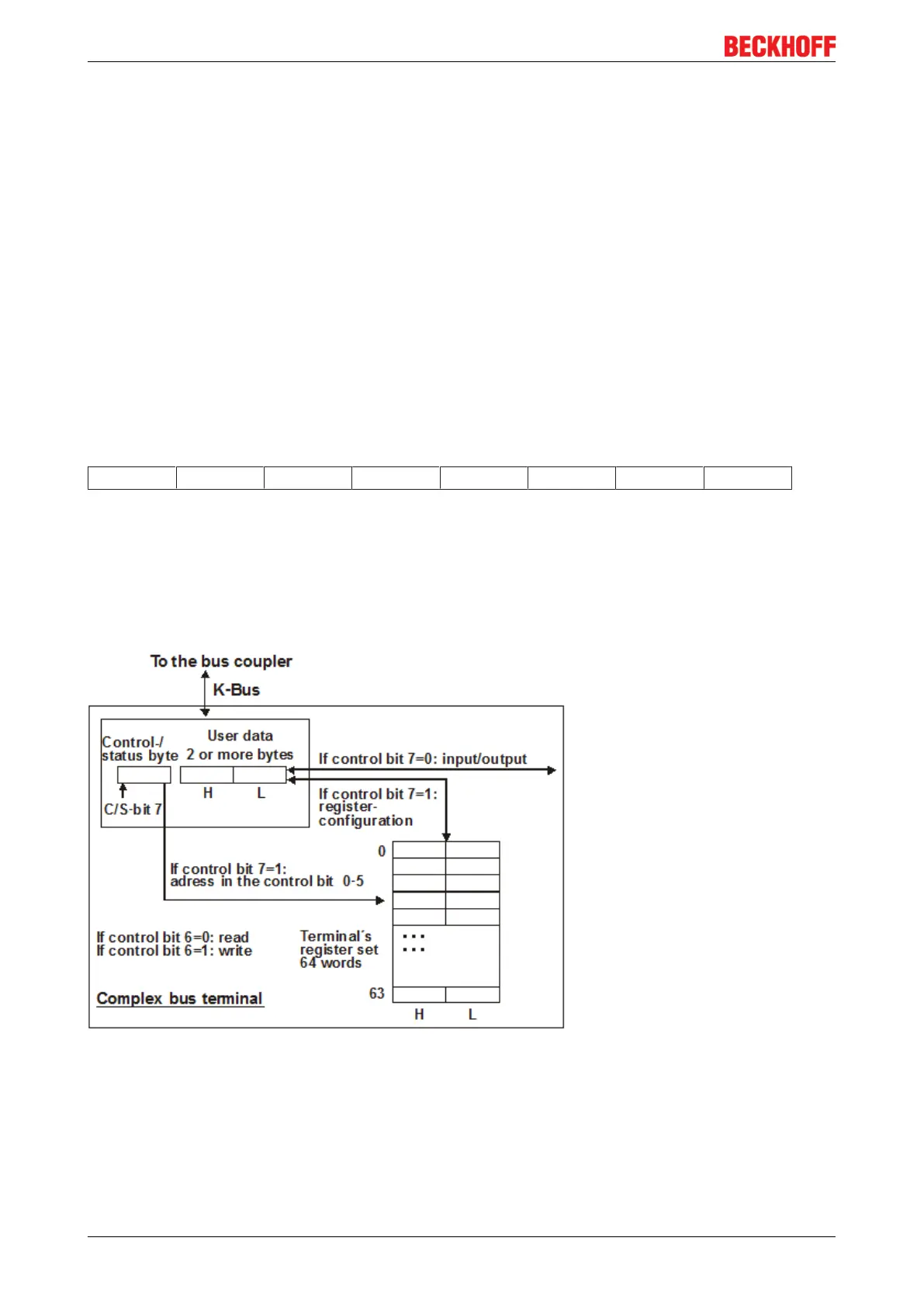
• Bit 7=1: Register mode
If bit 7 of the control byte is set, the first two bytes of the user data are not used for process data
exchange but written into the register set of the terminal or read from it.
• Bit 6=0: read, bit 6=1: write
Bit 6 of the control bytes is used to specify whether a register should be read or written.
◦ Bit 6=0: A register is read without changing it. The value can be found in the input process
image.
◦ Bit 6=1: The user data are written into a register. The process is complete once the status
byte in the input process image has returned an acknowledgment (see example).
• Bit 0 to 5: Address
The address of the register to be addressed is entered in bits 0 to 5 of the control byte.
Control byte in register mode (REG=1)
MSB
REG=1 W/R A5 A4 A3 A2 A1 A0
REG = 0
bin
: Process data exchange
REG = 1
bin
: Access to register structure
W/R = 0
bin
: Read register
W/R = 1
bin
: Write register
A5..A0 = register address
Addresses A5...A0 can be used to address a total of 64 registers.
Fig.20: Register mode control byte
The control or status byte occupies the lowest address of a logical channel. The corresponding register
values are located in the following 2 data bytes. (The BK2000 is an exception: here, an unused data byte is
inserted after the control or status byte, and the register value is therefore placed on a word boundary).
 Loading...