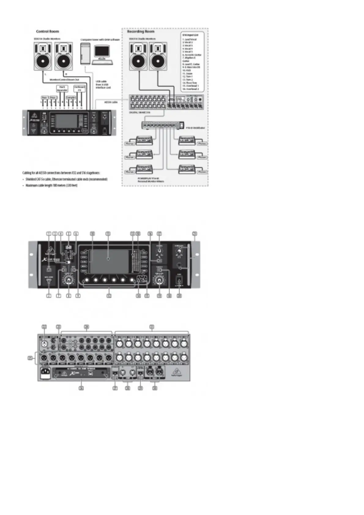
X32 RACK Recording Studio Setup
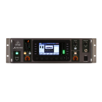
Step 2: Controls
1. USB button opens the Recorder View onb the MAIN DISPLAY, causing the LED to glow green. The LED will glow red to indicate
access on the DATA/AUDIO input. An unlit LED indicates no data access and inactive Recorder View.
2. DATA/AUDIO USB input allows connection of USB flash drives for firmware updates, loading/saving scenes and show files ,and
playing back or recording WAV files.
3. CHANNEL SELECT control cycles through all channels by turning the knob. By pressing this knob, you can jump to the next type of
channels.
4. CHANNEL TYPE LEDs indicate which type of channel is currently selected.
5. CHANNEL NUMBER display shows the currently selected channel.
6. INPUT METER displays the pre-fader input level of the selected channel.
7. SOLO button routes the currently selected channel to the monitoring paths. The LED lights when active.
8. CHANNEL LEVEL control adjusts the currently selected channel’s output.
9. MUTE button mutes the currently selected channel. The LED lights when active.
10. MAIN MENU buttons open specific menus on the MAIN DISPLAY.