6 XENYX 1202/1002/802/502 User Manual
1.3.3 Online Registration
Please register your new BEHRINGER equipment right after your purchase
by visiting http://behringer.com and read the terms and conditions of our
warrantycarefully.
Should your BEHRINGER product malfunction, it is our intention to have it
repaired as quickly as possible. To arrange for warranty service, please contact
the BEHRINGER retailer from whom the equipment was purchased. Shouldyour
BEHRINGER dealer not be located in your vicinity, you may directly contact
one of our subsidiaries. Corresponding contact information is included in the
original equipment packaging (Global Contact Information/European Contact
Information). Should your country not be listed, please contact the distributor
nearest you. A list of distributors can be found in the support area of our website
(http://behringer.com).
Registering your purchase and equipment with us helps us process your repair
claims more quickly and eciently.
Thank you for your cooperation!
2. Control Elements and Connectors
This chapter describes the various control elements of your mixing console.
Allcontrols, switches and connectors will be discussed in detail.
2.1 Mono channels
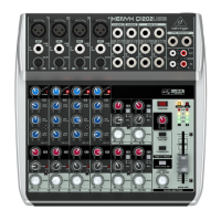
2.1.1 Microphone and line inputs
Fig. 2.1: Connectors and controls of mic/line inputs
MIC
Each mono input channel oers a balanced microphone input via the XLR
connector and also features switchable +48 V phantom power supply for
condenser microphones. TheXENYX preamps provide undistorted and noise-free
gain as is typically known only from costly outboardpreamps.
◊ Please mute your playback system before you activate the phantom
power supply to prevent switch-on thumps being directed to your
loudspeakers. Please also note the instructions in chapter 2.3.5
“Phantom power and LED displays”.
LINE IN
Each mono input also features a balanced line input on a ¼" connector.
Unbalanced devices (mono jacks) can also be connected to these inputs.
◊ Please remember that you can only use either the microphone
or the line input of a channel at any one time. You can never use
both simultaneously!
GAIN
Use the GAIN control to adjust the input gain. This control should always be
turned fully counterclockwise whenever you connect or disconnect a signal
source to one of the inputs.
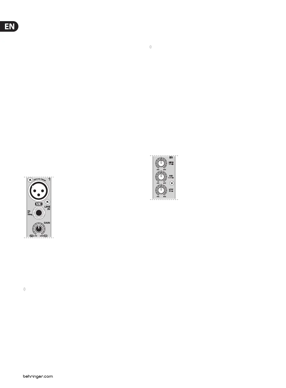
2.1.2 Equalizer
All mono input channels include a 3-band equalizer, except for the 502, which is
equipped with a 2-band EQ. All bands provide boost or cut of up to 15 dB. Inthe
central position, the equalizer is inactive.
The circuitry of the British EQs is based on the technology used in the best-known
top-of-the-line consoles and providing a warm sound without any unwanted
side eects. The result are extremely musical equalizers which, unlike simple
equalizers, cause no side eects such as phase shifting or bandwidth limitation,
even with extreme gain settings of ±15 dB.
Fig. 2.2: The equalizer of the mono input channels
EQ
The upper (HIGH) and the lower band (LOW) are shelving lters that increase
or decrease all frequencies above or below their cut-o frequency. The cut-o
frequencies of the upper and lower band are 12 kHz and 80Hz respectively.
Themid band (1202/1002/802) is congured as a peak lter with a center
frequency of 2.5 kHz.
LOW CUT
In addition, the mono channels (1202 and 1002) are equipped with a steep
LOWCUT lter (slope at 18 dB/oct., -3 dB at 75 Hz) designed to eliminate
unwanted low-frequency signal components.
 Loading...