Do you have a question about the Bell Console 500 and is the answer not in the manual?
Details on removing the battery cover, installing the 3V battery, and restarting the microprocessor.
Instructions for installing the 12V battery in the wheel transmitter and securing the cap.
Guidance on clamping the magnet to the spoke and attaching the transmitter to the fork, ensuring proper alignment.
Instructions for mounting the bracket onto the handlebar using the provided accessories.
Instructions for mounting the bracket onto the stem using the provided accessories.
Details on how to attach the cadence magnet (D) to the crankarm for proper signal detection.
Instructions for securing the cadence sensor (F) to the bicycle frame, ensuring correct alignment with the magnet.
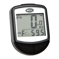
Explains two methods to obtain the wheel factor: using a provided chart or a manual measurement technique.
A table listing various wheel diameters and their corresponding wheel factor values for easy input.
Configuration of the 12 or 24-hour clock format and time setting.
Setting up periodic maintenance alerts for the bicycle, indicated by a wrench icon.
Procedure for setting the total distance (ODO) after battery replacement and wheel size input.
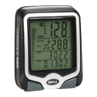
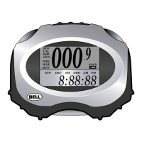
Details the three primary display screens and the information presented on each.
Explanation of how current and average cadence (RPM) are displayed and monitored.
How the speed comparator indicates if current speed is faster or slower than average speed.
Description of the cyclist icon indicating acceleration or deceleration.
Details on setting and responding to maintenance alerts for bicycle upkeep.
How to activate and use the scan mode to cycle through all display screens automatically.
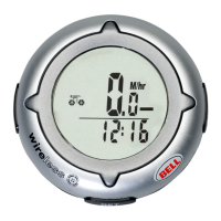
Information on the 12/24 hour clock and instantaneous speedometer readings.
Instructions for resetting the total distance (ODO) and trip distance (DST).
How the maximum speed (MXS) is stored and reset.
Explanation of how average speed (AVS) is calculated using trip timer and tripometer.
Details on the trip timer (TM) and the auto start/stop feature for battery saving.
Guidance on resolving issues such as no cadence, inaccurate readings, or display problems.
| Brand | Bell |
|---|---|
| Model | Console 500 |
| Category | Bicycle Accessories |
| Language | English |