FIGURE 25
B. CONTROL BOX, WIRING (FIGURE 24-a & 24-b).
WARNING:
MAKE SURE THE POWER SUPPLY IS TURNED OFF AT THE CENTRAL
DISTRIBUTION PANEL.
1. Strip approximately 10mm of insulation off the power supply leads and interconnecting cables.
2. Following wiring diagram, connect those wires to the terminal block of control box.
3. Set the restriction plate to the original place.
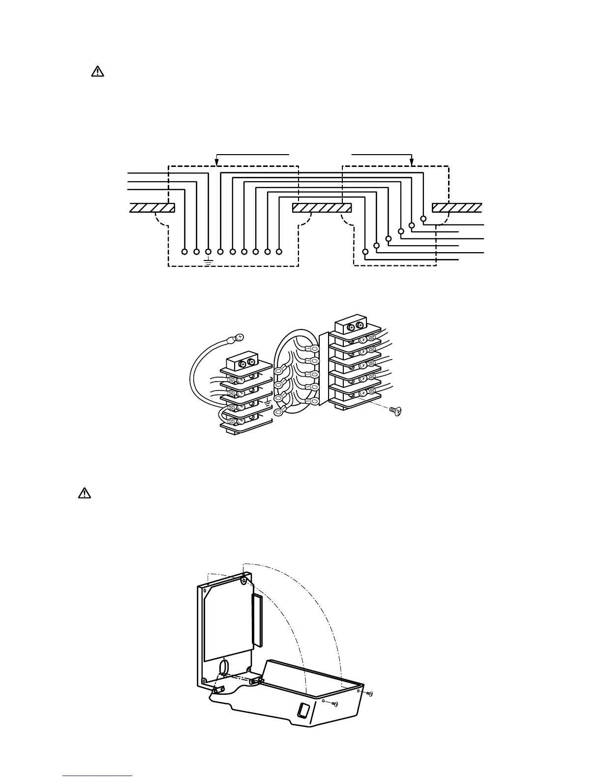
C. CLOSING FRONT PANEL (FIGURE 25).
CAUTION:
BEFORE CLOSING THE FRONT PANEL, PERFORM POST INSTALLATION
CONFIRMATION(PAGE 25 ).
1. Conrm all the post installation conrmation are performed.
2. Close the front panel and secure two M3 phillips head screws on the top panel.