[3] LOCATION OF COMPONENTS
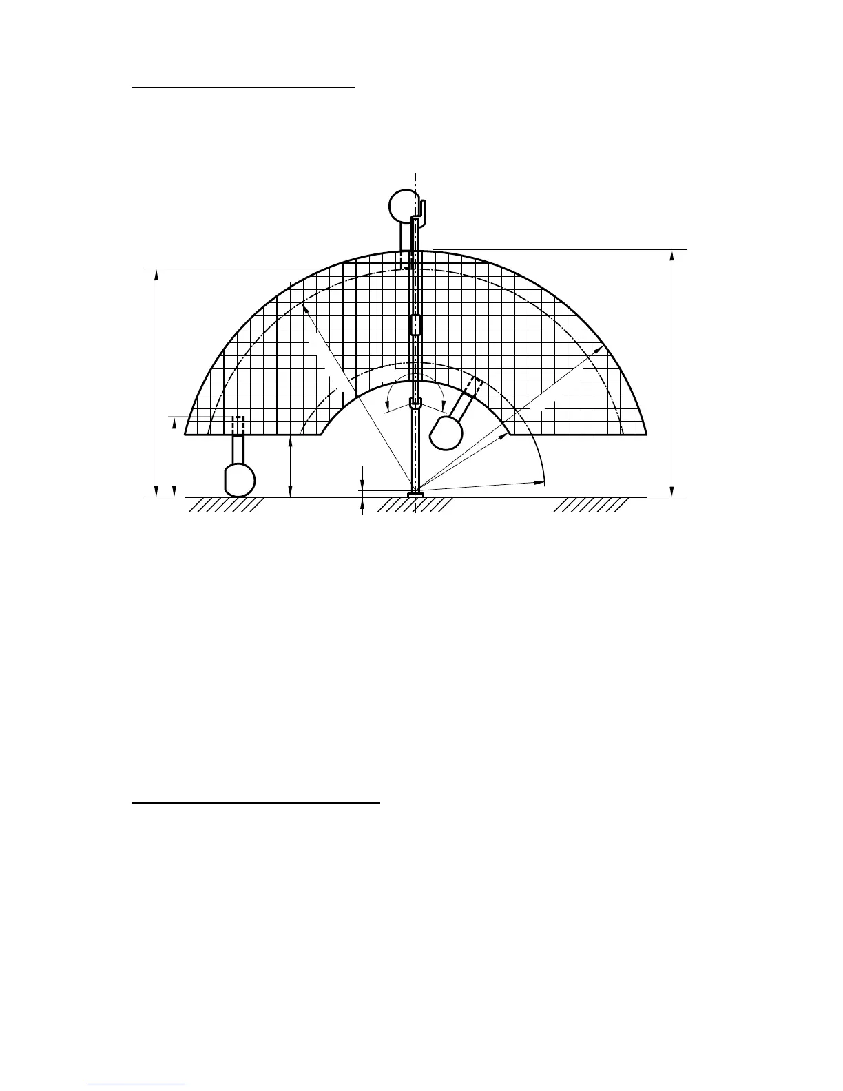
A. Arm and head assemblies for WK type:
Using the information provided in FIGURE 1, determine the correct location for the installation of
the arm and head assemblies for WK type. (unit : mm)
NOTE:
Local requirements supersede guide lines indicated below.
B. Control box :
When determining the location for the control box the following radiation requirements concerning
operator positioning must be considered. The operator must;
1. have full view of the patient.
2. have full view of kVp, mA, timer selections and exposure warning light.
3. be a minimum of 1.8 meter away from the patient.
4. be out of line of the useful beam of radiation or be positioned behind a protective device with
X-ray protection equivalent of 1 mm of lead.
FIGURE 1
SECTION THREE : INSTALLATION INSTRUCTIONS
Within the installation and conrmation procedures are inspection/test steps which the installer must
perform to insure that the installation meets the manufacturer’s specications.
[1] INSTALLATION REQUIREMENTS
Tools:
Standard tool kit including wire crimping pliers (AMP, “Super Champ” or equivalent).
1.5 mm, 2 mm, 3 mm and 5 mm allen keys.
Instruments:
Digital multimeter with an accuracy of 1%, capable of measuring 300 V AC, and capable of indicat-
ing true RMS value within 1 second.
Standard calculator.
POWER SUPPLY:
Prior to starting the installation inspect the power supply and conrm that the power supply is with
rated line voltage ±10%, and that the supply is a 3 wire EARTHED circuit, separately connected to
the central distribution panel with an overcurrent protection device.
From 2004 July