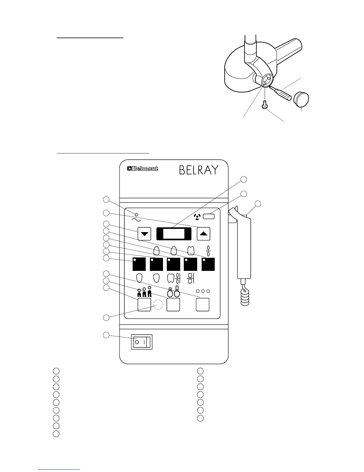
SECTION FIVE : CONTROL IDENTIFICATION AND OPERATION
[1] CONTROL IDENTIFICATION
Patient Size Selection Switch
Cone Type Selection Switch
Exposure Time Adjusting Sw.(Up)
Film Speed Selection Switch
Exposure Time Adjusting Sw.(Down)
Exposure Time Display Window
Tooth Selection Switch (T1)
Tooth Selection Switch (T2)
Tooth Selection Switch (T3)
Tooth Selection Switch (T4)
Tooth Selection Switch (T5)
W A R N I N G
THIS X-RAY UNIT MAY BE DANGEROUS
TO PATIENT AND OPERATOR UNLESS SAFE EXPOSURE FACTORS
AND OPERATING INSTRUCTIONS ARE OBSERVED.
MODEL 096 70kVp 10mA
P C F
T1 T2 T3 T4 T5
a
b
c
15
14
2
3
4
9
8
7
6
12
11
10
16
5
1
13
[3] HEAD POSITIONING
A. Place head into position.
B. If head drifts from the set position, adjust the brake screws
according to the following procedures.
1. Remove the yoke outside cover by loosening cover
screw.
2. Adjust 6 brake screws using phillips screw driver.
3. After adjustment, reattach the yoke outside cover with
the cover screw.
FIGURE 28
Phillips Screw Driver
Yoke Outside Cover
Cover Screw
Brake Screw