–
17
–
[5] CONTROL BOX INSTALLATION
The wall and the strength of the hardware used must be checked and veried as being adequate to
withstand a 10 kg shear load.
A flush mounted junction box with the necessary conduit and wiring must be pre-installed at
1310mm from the oor.
NOTE:
Refer to the control box template, and:
1. Be certain the electrical wire entry hole is aligned with the junction box.
2. That there is adequate support in the wall to secure the control box.
A. CONTROL BOX - MOUNTING for WK type0 (FIGURE 23):
1. Tape the control box template to the wall at the recommended height.
1a. Conrm relationship of access hole in for the electric wires with the entry hole for the wires in
the back of the control box.
2. Using a 2.4mm drill, drill a pilot hole 50mm deep for each mounting screw.
2a. The method of drilling the pilot hole and, the hardware use to secure the control box depend
upon the structure.
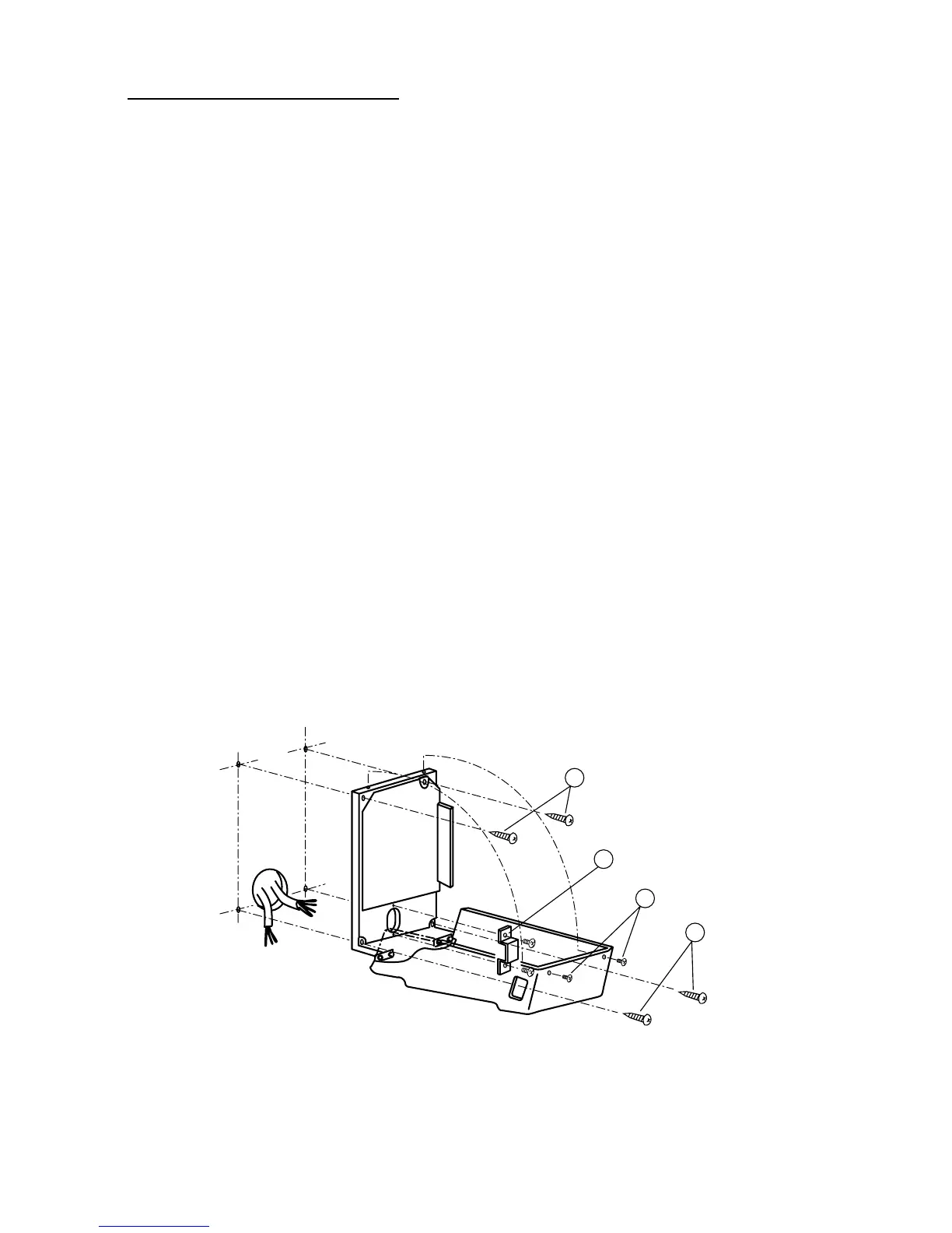
3. Drive two wood screws into upper two holes remaining about 20mm undriven. (Fig.23a)
4. Remove two M3 Phillips head screws from top of the control box and open front panel. (Fig.23b)
5. Remove a restriction plate. (Fig.23c)
6. Snake power supply cable lines and interconnecting wires through access hole in back panel.
7. Hook the control box chassis to wood screws driven in step 3 above through two mounting holes
on upper side of chassis. Tighten screws slightly.
8. Attach two wood screws to mounting holes on lower side of back panel. (Do not fully tighten.)
(Fig.23d)
9. Placing level across top edge of the control box, level, then tighten four screwes securely.