–
7
–
SECTION TWO : PRE-INSTALLATION INSTRUCTIONS
[1] SUPPORT REQUIREMENTS
Control box:
When mounting the MODEL 096 WK control box, the wall and mounting hardware must be sufcient
to withstand a 12 kg shear load.
Arm and head:
(1) Wall mount type (WK)
The wall and mounting hardware for arm mounting bracket must be sufcient to withstand a 45 kg
shear load and a 200 kg withdrawal force at each of the three mounting bolts. If wall dose not have
enough strength, use the wall mounting plate(option). This plate is designed for mounting on two 2
X 4 wood studs with 16 inch center. With this plate, wall and mounting hardware must be sufcient
to withstand a 45 kg shear load and a 200 kg withdrawal force at each of the four mounting bolts.
(2) Ceiling mount type (CK)
The ceiling and mounting hardware for mounting plate must be sufcient to withstand a 150 kg (330
pounds) withdrawal force.
(3) Floor mount type (FK1)
The oor and mounting hardware for oor mounting plate must be sufcient to withstand a 100 kg
(220 pounds) withdrawal force.
:
If the MODEL 096 is to be mounted in a manner other than what is specied in this manual or if
the hardware to be used is other than what is supplied, the support capability of the wall and
the strength of the hardware must be checked and veried to be adequate.
[2] ELECTRICAL REQUIREMENTS
Power supply:
The MODEL 096 x-ray system will operate on a power supply of rated line voltage ± 10% with a three
wire (hot, neutral, earth) circuit, separately connected to the central distribution panel with an over cur-
rent protection device. Use sufcient wire size as the line voltage regulation should be within the range
of 2~5 % for 120V, 0~3% for 220~240V at rated current.
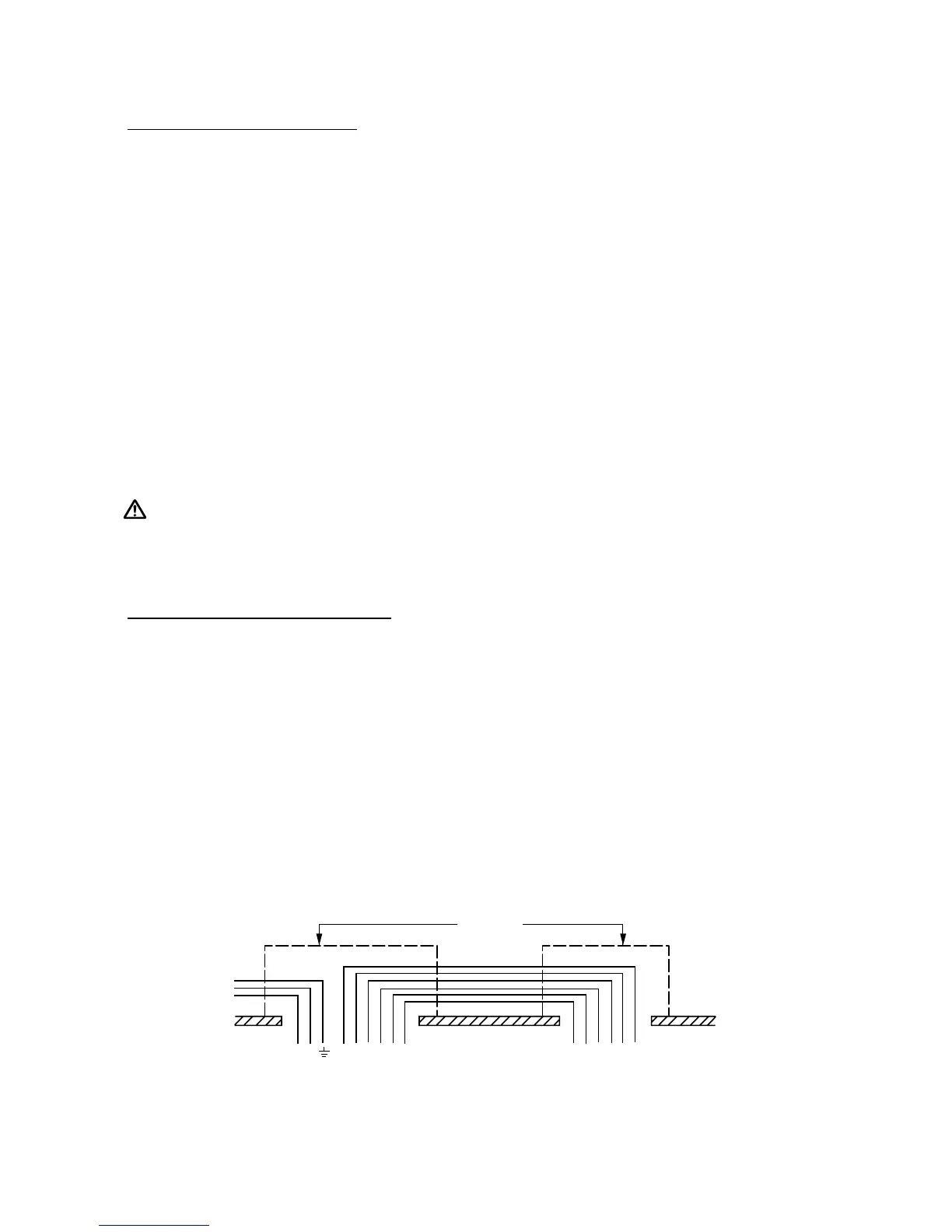
Concealed wiring for WK type:
Concealed wiring is accomplished by bringing conduit and wires into (2) ush mounted junction boxes
located (1) behind the control box and (1) behind the arm mounting bracket. Recommended heights for
the
ush junction boxes are : 131cm for behind control box and 113cm for behind arm mounting bracket.
Wiring done in this manner should extend 30cm beyond the wall surface to allow sufcient wire for
connections.
NOTE:
All connections, workmanship and materials used must comply with the local codes.