–
19
–
SECTION FOUR: POST INSTALLATION INSPECTION
[1] ARM ASSEMBLY
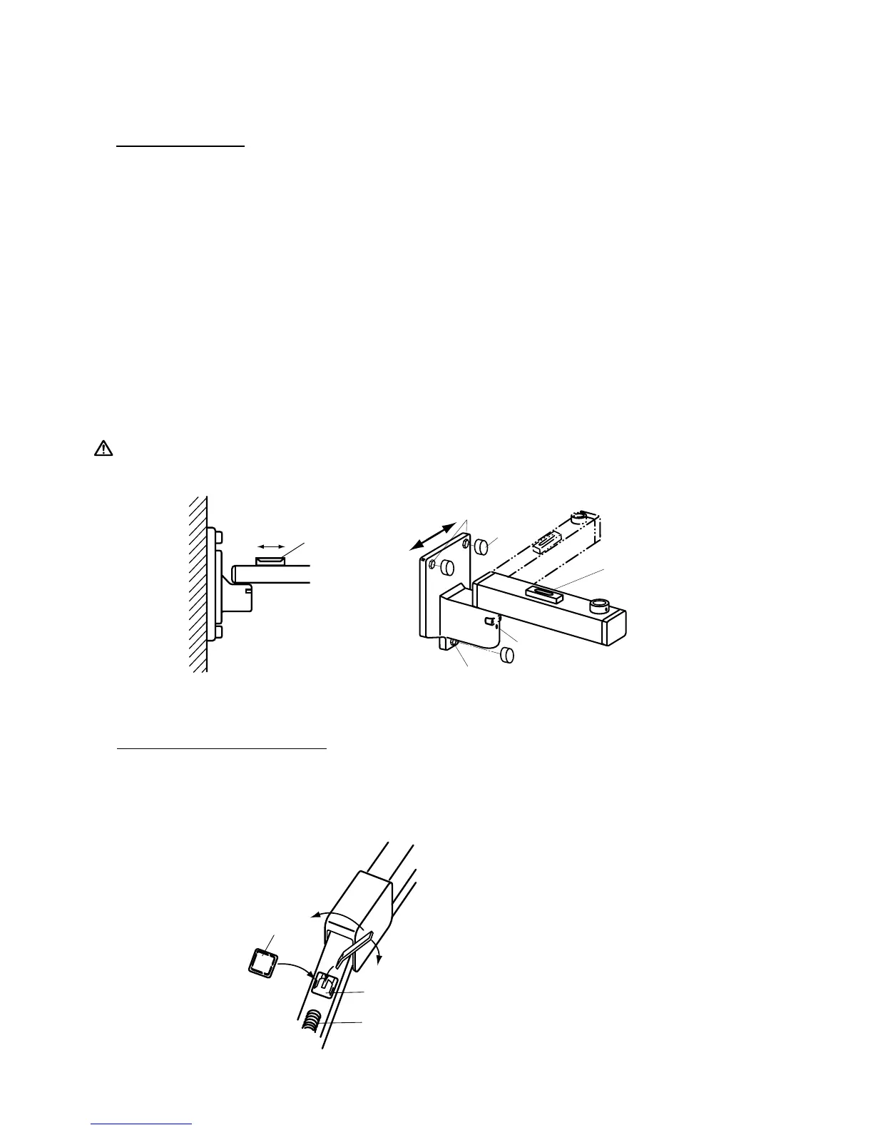
1. Incorrect levelling of the wall bracket can cause arm drift. First, check level with arms in position
#l . If not correct, bracket must be adjusted by placing shims behind the arm mounting bracket or
the wall plate (FIGURE 26-a).
IMPORTANT:
If the end of the horizontal arm #1 is pitched below level, then the tubehead will drift away from
the wall. If the end of the horizontal arm #1 is pitched above level, then the level arm will require
only minimum adjustment of brake (friction) screw.
2. Check level in position #2. If not correct, adjust as follows: (FIGURE 26-b)
a) Remove bolt caps on mounting bolts.
b) SLIGHTLY loosen two top mounting bolts.
c) Shift the bracket left or right up to the arms arc accurately levelled.
d) Move the horizontal arm to position #1.
e) Fully tighten two top mounting bolts.
f) Fully tighten bottom mounting bolt.
g) Put the bolt cap to each head of mounting bolt.
NOTE:
SLIGHT TENDENCIES TO DRIFT CAN BE CORRECTED BY TIGHTENING
BRAKE SCREWS IN HORIZONTAL ARM AND/OR WALL BRACKET.
DO NOT TIGHTEN BEYOND WHAT IS REQUIRED TO PREVENT DRIFT.
FIGURE 27
[2] BALANCE ARM ASSEMBLY
1. Place the balance arm assembly into position.
2. If either balance arm drifts either higher or lower from the set position, remove the spring adjuster
covers and with the supplied wrench adjust the balance arm springs (FIGURE 27).