1268-600
VARIABLE SPEED JIGSAW
12
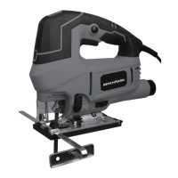
2. Bevel angles (3) are marked on a scale located on the side of the base (Fig. 4).
3. Slide the base toward the front of the jig saw and align the bevel angle with
the edge of the base (4).
4
3
Fig. 4
4. Slide the base backward to engage the bevel angle slot (5) with the
indexing pin (6) (Fig. 5)
5
Fig. 5
NOTES:
a) Use a protractor to check the bevel angle between the blade and the base.
b) To set the bevel angle at intermediate angles, do not slide the base backward.
5. Once the desired bevel angle is obtained, lock the base by pressing the
quick release lever into the sole plate.
6. Make a test cut in a scrap workpiece and measure the bevel angle.
Adjust the bevel angle if necessary.
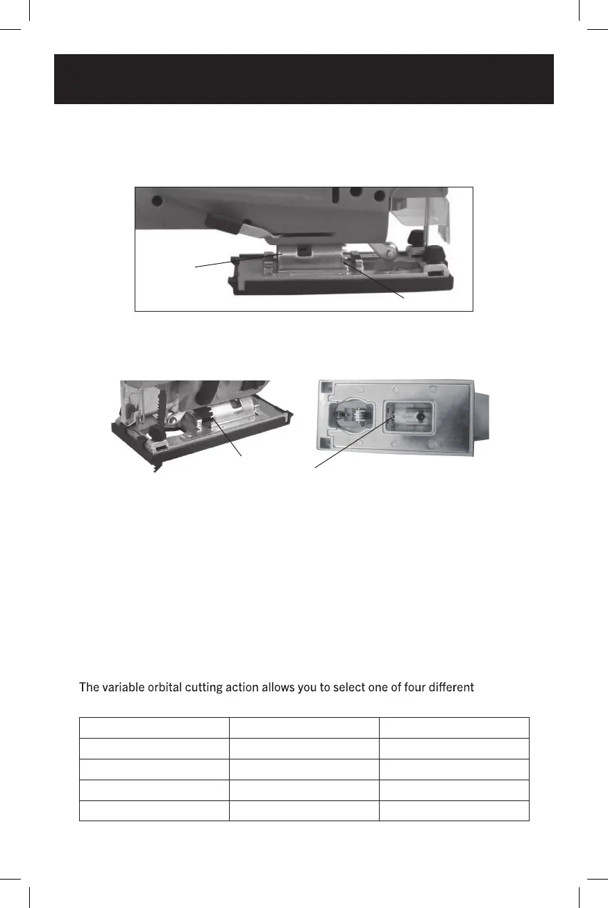
SETTING THE ORBITAL CUTTING ANGLE
blade angles.
Position Angle Material
0 Neutral Metal
1 Small Hard wood
2 Large Soft wood
3 Full Styrofoam
6