Do you have a question about the Bender AGH420 and is the answer not in the manual?
Explanation of danger symbols (DANGER, WARNING, CAUTION) and their meanings.
Details for contacting first-level technical support via phone or email.
Description of the device's intended application and operational limits.
Rules for skilled persons performing work on electrical installations.
Warning about the risk of electric shock and necessary precautions.
Key features and technical specifications of the device.
Detailed explanation of how the device functions and its monitoring capabilities.
Explanation of how insulation resistance is monitored and alarm conditions.
Information about the device's self-test feature and error code meanings.
How alarms are assigned to relays and LED indicators.
Description of the voltage monitoring functions and alarm triggers.
Visual representation of the device's electrical connections.
Steps to follow for commissioning the device after installation.
Warning about hot surfaces and precautions when the device is energized.
How to read data from the device using Modbus registers.
How to write parameters to the device using Modbus registers.
Example of a Modbus response after a write command.
Example of a Modbus write request from master to device.
Details on the specific data types and formats used by the device.
Description of the IsoData string structure and the meaning of its components.
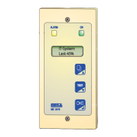
Description of the device's front panel display and indicators.
Overview of the device's menu system and navigation.
Menu for querying and setting response values like resistance and voltage limits.
Menu for configuring fault memory, alarm relays, and interfaces.
Detailed configuration of response values for alarms and pre-alarms.
Assigning alarms to relays and configuring LED indicators.
Settings for communication interfaces like BMS, Modbus, and IsoData.
Setting up start-up delay, response delay, and delay on release.
Configuring password, system connection test, and device test.
| Brand | Bender |
|---|---|
| Model | AGH420 |
| Category | Measuring Instruments |
| Language | English |


 Loading...