3
MK2430_D00129_00_Q_DEEN/12.2014
COMTRAXX® MK2430
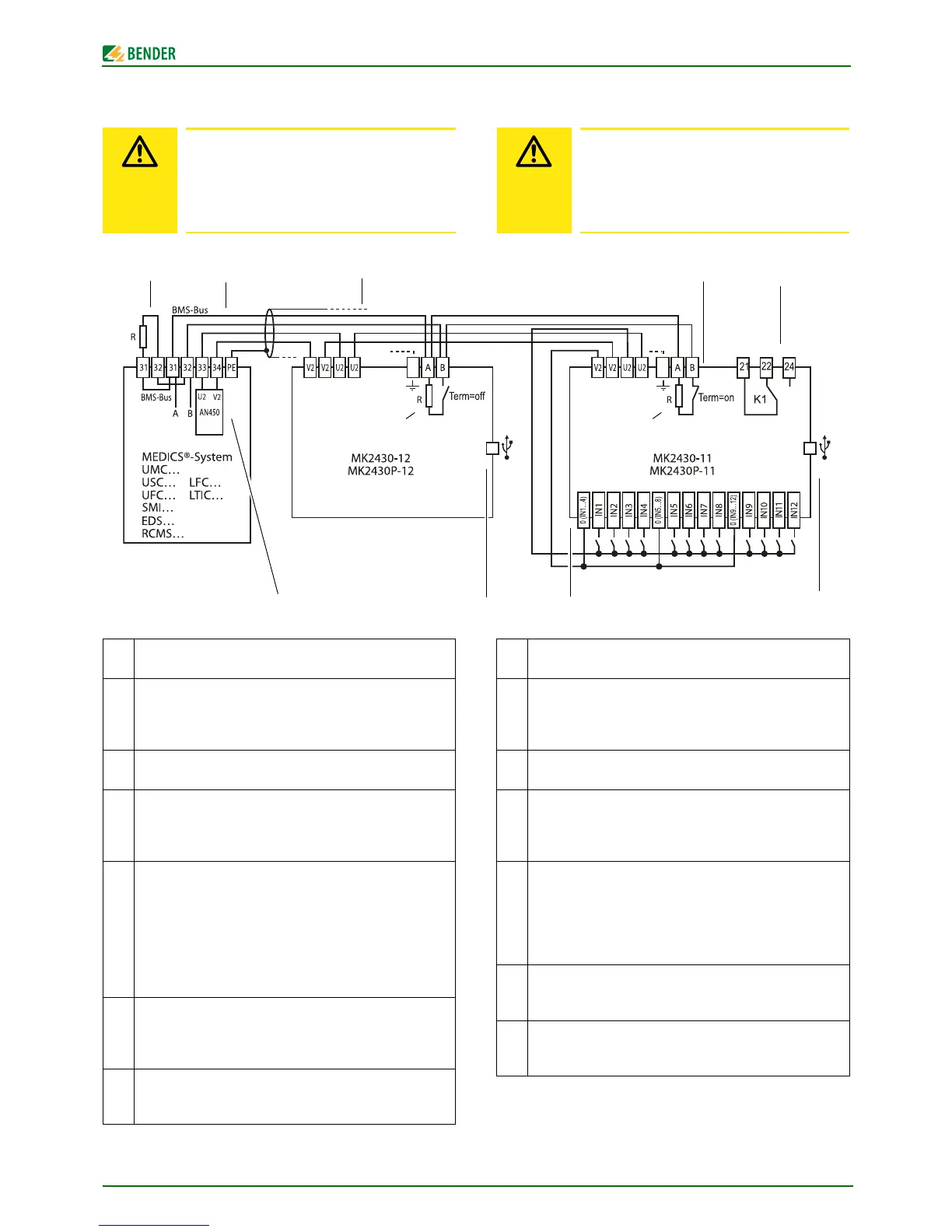
Connection example
* Devices without BMS bus connection, but with test input (e.g. ISO-
METER®)
Make sure that the power supply of the MK2430 is
isolated from earth (PE) (safety extra-low volt-
age SELV). If this is not taken into consideration
and if a PC is connected to the USB interface, the
MK 2430 device and the PC may be damaged.
1 Terminating resistor BMS bus (R = 120 Ω), can be connected
via DIP switch on the MK2430.
2 BMS bus connection (Bender Measuring Device Interface) for
communication with other Bender devices, such as: insulation
monitoring devices 107TD47, control devices PRC487, residual
current monitors RCMS470 …
3 Power supply unit in the MEDICS® module, sufficient for sup-
plying power to at least three MK2430s.
4 Cable between the MEDICS® module and MK2430. Please
observe the permissible cable lengths and cross sections when
using the AN450 or AN410 power supply units in MEDICS®
modules.
5 Digital inputs. The digital inputs may be activated either via
internal or external voltage or potential-free contacts. If the
inputs are activated via an external voltage, the common 0(-) is
applied to terminal "0" and the 1(+) signal to the relevant input
IN1 … IN12. In this case, the connections between terminals 0
and V2, and the common connections and U2 are not required.
6 USB interface. For PC connection. The TMK-SET PC software is
used to program the MK2430. You can use the PC software
TMK-HISTORY to read out the MK2430 history memory.
7 MK2430-11 only: Relay output. Programmable contact for
device errors, test of assigned devices*, device failure and com-
mon alarm message.
Anschlussbeispiel
* Geräte ohne BMS-Bus-Anschluss, aber mit Test-Eingang (z. B. ISO-
METER®)
Stellen Sie sicher, dass die Spannungsversorgung
der MK2430 gegen PE isoliert ist (Sicherheits-
kleinspannung SELV). Wird dies nicht beachtet
und ein PC an die USB-Schnittstelle angeschlos-
sen, so drohen Sachschäden an der MK2430 und
dem PC.
1 Abschlusswiderstand BMS-Bus (R = 120 Ω), in der MK2430
über DIP-Schalter zuschaltbar
2 Anschluss BMS-Bus (Bender-Messgeräte-Schnittstelle) zur
Kommunikation mit anderen Bender-Geräten, wie z. B.: Isolati-
onsüberwachungsgeräten 107TD47, Steuergeräten PRC487,
Differenzstrom-Auswertegeräten RCMS470 …
3 Netzteil im MEDICS®-Modul, ausreichend für die Versorgung
von max. drei MK2430.
4 Leitung zwischen MEDICS®-Modul und MK2430. Beachten Sie
bei der Versorgung der MK2430 durch das Netzteil AN450 bzw.
AN410 in den MEDICS®-Modulen die zulässigen Leitungslän-
gen und Querschnitte.
5 Digitale Eingänge. Die digitalen Eingänge können durch eine
interne oder externe Spannung und potentialfreie Kontakte
angesteuert werden. Werden die Eingänge über eine externe
Spannung angesteuert, wird der gemeinsame 0(-) auf die
Klemme „0“ gelegt und das 1(+)-Signal auf den jeweiligen Ein-
gang IN1 … IN12. In diesem Fall entfallen die Verbindungen
zwischen den Klemmen 0 und V2, die gemeinsamen Verbin-
dungen und U2.
6 USB-Schnittstelle. Dient zum Anschluss eines PCs. Mit der PC-
Software TMK-SET wird die MK2430 programmiert. Mit der PC-
Software TMK-History wird der Historienspeicher der MK2430
ausgelesen.
7 Nur MK2430-11: Relaisausgang. Programmierbarer Kontakt für
Gerätefehler, Test zugeordneter Geräte*, Geräteausfall und
Sammel-Alarmmeldung

 Loading...


