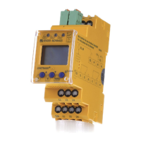
Do you have a question about the Bender EDS3090 and is the answer not in the manual?
Describes connecting and operating portable equipment for insulation fault location.
Explains symbols used in the manual for important instructions and information.
Provides a summary of the manual's chapters and their content.
Specifies the portable insulation fault location system's intended applications and limitations.
Details hazards related to high locating current/voltage and sensitive components.
Refers to important safety instructions document accompanying the manual.
Specifies that only qualified electricians should operate the EDS3090 devices.
Provides an overview of the EDS309x system components.
Lists different EDS309x variants and their permissible system voltages.
Information on standard and optional accessories for the system.
Describes the function of the PGH18... in generating locating current.
Explains the measuring functions of the EDS195P.
Details the function and specifications of measuring clamps.
Explains how AGE185 expands voltage range for insulation fault location.
Illustrates the EDS system with a schematic diagram.
Describes the duration and sequence of the locating current pulse.
Defines key terms like IAL, IAn, and I.
Shows the path of residual and locating currents in the system.
Explains the functional sequence of the insulation fault location equipment.
Lists requirements for accurate insulation fault detection.
Discusses setting reduced locating current for sensitive systems.
Explains how system parameters affect EDS195P response sensitivity.
Shows response curves for main circuits in AC systems.
Shows response curves for main circuits in DC systems.
Provides response curves for control circuits in AC systems.
Shows response curves for control circuits in DC systems.
Explains how to disconnect insulation monitoring devices.
Describes connecting the injector in isolated IT systems.
Details the connection procedure for live IT systems.
Explains how to connect the system to a PV system.
Briefly outlines the EDS mode for insulation fault location.
Provides detailed information on using EDS309... in various system types.
Explains how to perform residual current measurements with EDS195P.
Details the displays and controls on the PGH18... unit.
Details the displays and controls on the EDS195P unit.
Instructions for powering the EDS195P on and off.
Details two methods for changing the measuring clamp.
Guides on switching between IAL and Ion modes.
Method to quickly check response values.
Information available in the Info menu.
Shows standard display configurations for EDS measurement.
Shows standard display configurations for residual current measurement.
Explains how to navigate through the EDS195P menu system.
Details parameters configurable in the 'Settings' menu.
Options for language, clock, and contrast settings.
Menu for displaying harmonic information.
How to check recorded alarms for insulation fault location.
How to check recorded values for residual current measurement.
Steps for insulation fault location in systems without permanent EDS.
Steps for insulation fault location with permanent EDS systems.
Guides insulation fault location in diode-decoupled DC systems.
How to use the EDS195P for residual current measurement.
How to measure and display harmonics during RCM.
How the EDS195P displays battery charge status.
Instructions for replacing the batteries in the EDS195P.
Information about the supplied power supply unit.
Technical data for EDS309 system components.
Technical specifications for the PGH18... locating current injector.
Technical specifications for the EDS195P insulation fault locator.
Technical specifications for the various measuring clamps.
Technical specifications for the AGE185 coupling device.
Lists applicable national and international standards.
| Brand | Bender |
|---|---|
| Model | EDS3090 |
| Category | Measuring Instruments |
| Language | English |


