10
TGH1266E - 05/04
3
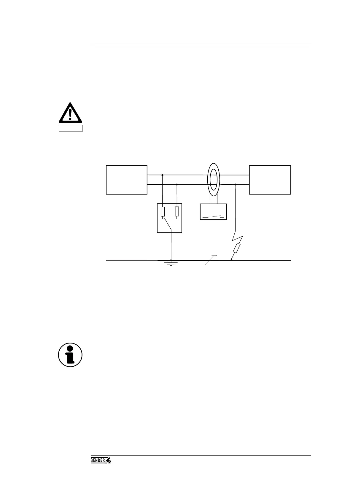
Operating Principle of the EDS3065
Operating Principle
of Insulation Fault
Location
IT-System
AC/DC
Consumer
Evaluator
Test device
PGH185
PE
R
F
EDS165
measuring clamp, measuring current transformer
Response Values
Caution
When a first insulation fault occurs in IT systems, a fault current flows which is essentially
determined by the leakage capacitances of the system. The basic concept in fault location is therefore
to close the fault current circuit for a short period over a defined resistance. As a result of this
principle, the system voltage itself drives a test current which receives a signal that can be evaluated.
The test current is generated periodically by the PGH185 test device (which is a component of the
EDS3065 system). The test current is limited in amplitude and time. As this happens, the system
conductors are connected alternately to earth over a defined resistance. The fault current which is
generated in this manner depends on the size of the insulation fault present, and on the system
voltage. It is limited to a maximum of 25 mA, and when I
max
= 10mA is set, it is limited to 10 mA.
For planning purposes, it should be noted that no system components are present in which this test
current can bring about a damaging reaction, even in unfavourable cases.
The test current pulse flows from the test device via the ‘live’ leads, taking the shortest path to the
location of the insulation fault. From there, it flows via the insulation fault and the earth lead (PE
conductor) back to the test device. This current pulse is then detected by the clamp-on probes or
measuring current transformers located in the insulation fault path, and is reported by the connected
EDS165 evaluator.
The clamp-on probes and/or measuring current transformers are used as residual current transformers
- that is to say, the PE conductor is not passed through the transformer.
Important: normal commercial clamp-on probes or measuring current transformers must not be
used.
The response value is determined by the sensitivity of the EDS165 evaluator. In DC as well as AC
and 3 AC systems, this is 5 mA as an arithmetic average value.
The accuracy is +/- 2 mA of the displayed measurement value. System faults and excessively high
system leakage capacitances may have a negative influence on the accuracy.