39
TGH1266E - 05/04
Practical Use
In some applications DC systems are diode decoupled. Between these decoupled circuits
compensating currents may occur. The quantity of the currents and its direction depend on the
system voltage, the characteristics of the diodes and the kind of loads installed in the system.
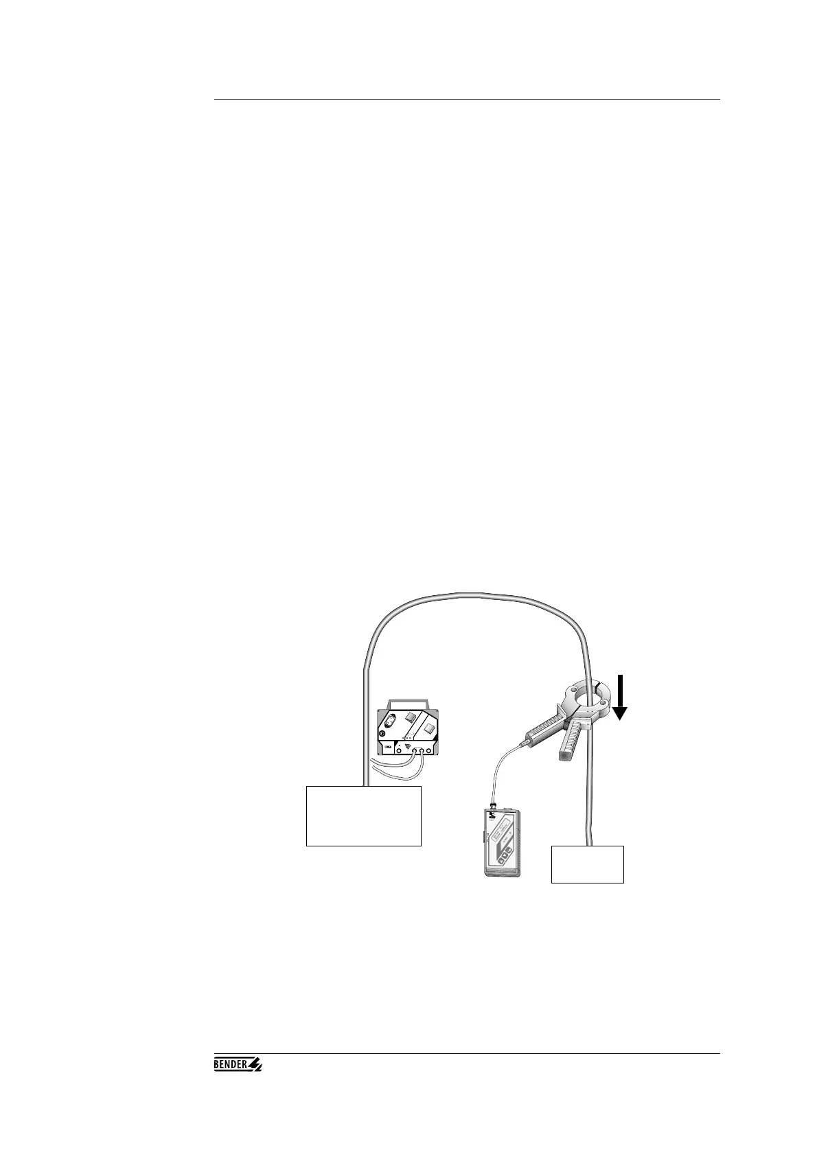
When the portable insulation fault location device EDS3065 is used in diode-decoupled
systems, the aforementioned compensating (or circulating) currents will disturb the EDS3065
and will cause measuring faults. Therefore BENDER recommends the use of the EDS3065 in
diode-decoupled system only according to the drawing on the previous page.
Additionally please consider the following:
• Always use two identical clamp-on probes. Caution: Do not forget
to set the correct clamp-on probe in the corresponding menu of
the EDS165.
• Use only 50Ω coaxial cable and a T-adaptor to connect both of the
clamp-on probes to the evaluating device EDS165.
• Do not exceed the max. length of the coaxial cable of 10 m per
clamp-on probe.
• Using two clamp-on probes according the BENDER drawing will
reduce the sensitivity of the EDS3065 by about 10 %.
• Always use the clamp-on probe in a way, that the energy flow direction
corresponds to the marking on the clamp-on probes (P1 => P2).
EDS3065 in diode
decoupled systems
Source IT-system
Load
PGH185
100
mA
10
mA
2
5
m
A
Im
ax
O
N
ON
U
s
L1(+
)
L2
(-)
L3
AC/DC
P1
P2