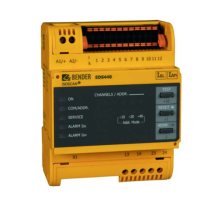
MountingMounting
EDS44x_D00201_07_M_XXDE/06.2020
18
5.5 Connection of the BB bus
The BB bus is an interface that enables Bender devices to communicate with each other.
The BB bus can be used with an ISOMETER® and a maximum of two EDS44x or one
EDS44x-S and one IOM44-S. For this purpose, the BB bus is installed at the rear side of
both devices and afterwards, both devices are mounted next to each other on the DIN
rail. For further information, refer to the quick-start guide enclosed to the BB bus PCBs.
Voltage supply via BB bus
Sensor variants that are additionally connected to the ISOMETER®, e.g.
EDS44x-S, do not require additional supply voltage when the devices are
connected to the BB bus via X3.
Number of devices to be connected
A maximum of two EDS44x-S or one EDS44x-S with one IOM441-S can be
connected to an ISOMETER®.
Mounting
When the BB bus is mounted, the EDS44x must always be mounted on
the right side of the ISOMETER®.
Error codes
In the case of the EDS44x-L variant, error codes of the BB bus are indicat-
ed by means of a combination of the SERVICE LED and various flashing
channel LEDs. See "Device error, BB bus error" on page 28.
5.6 Connection to the voltage supply
Back-up fuse voltage supply
If the device is supplied via an external power supply unit, the back-up
fuse F
back-up
at connection "A1/+ A2/-" must be selected in such a way that
the feeding power supply unit is able to trip the DC-compatible back-up
fuse.
Example: A back-up fuse of 650 mA/T is recommended when using a 24-V
power supply unit (min. 1 A).
1
U
s
= AC/DC 24...240 V
A1/+
F
A2/-
 Loading...