EDS44x_D00201_07_M_XXDE/06.2020
30
Commissioning
7. Commissioning
7.1 Before switching on
Before switching on the EDS44x, make sure that the following aspects have been consid-
ered:
• The connected supply voltage U
S
matches the information on the nameplates of the
devices.
• The maximum permissible nominal insulation voltage of the used measuring cur-
rent transformers and the ISOMETER® with integrated locating current injector is not
exceeded.
• The PE conductor is not routed through the measuring current transformer.
• Any magnetic fields that are nearby and could cause interference when mounting
the measuring current transformers have been taken into account.
• Regarding the BS bus node address settings, no address has been assigned twice.
The ISOMETER® with an integrated locating current injector (e.g. ISOMETER® iso685-
D-P) has been set as master.
CAUTION
Risk of overcurrent!
Devices connected to the analogue output must have a suitable protec-
tive circuit against overcurrent to protect the device in the event of a de-
fective analogue output.
Start the cyclic test of the EDS44x at regular intervals to ensure that the re-
lays work and switch correctly. (e.g. once a year)
7.2 Switching on
1. Switch on the supply voltage of all devices connected to the BS bus or the BB bus.
First, the "ON" LED flashes on the EDS44x. Subsequently, the "ON" LED lights up con-
tinuously.
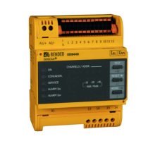
2. Eliminate all displayed insulation faults and device errors via the ISOMETER®. If the
response value is exceeded, the respective device error message is indicated on the
EDS44x-L by the alarm LED "
ALARM I
L
" or "ALARM I
n
", which lights up (see "Alarm
messages" on page 40).
– Further information regarding fault messages on the EDS44x can be displayed via the ISO-
METER®.
– Device errors may be caused by measuring current transformers not being connected.
Check the measuring current transformer connections. Disconnect the channels that are
not required
in the menu of the ISOMETER®.
Pending alarm messages may temporarily not be available due to syn-
chronisation processes on the BS bus. However, if the cause of the alarm
persists, the alarm messages reappear after a few seconds.
 Loading...