EDS44x_D00201_07_M_XXDE/06.2020
26
Display and alarm messages
6. Display and alarm messages
6.1 Operating and display elements EDS44x-S
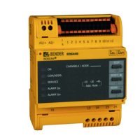
6.2 Operating and display elements EDS44x-L
-1
>3s
ADDR.
RESET
+1
+10
TEST
CHANNELS / ADDR.
12
11109
887
345621
+10 +20 +40
Addr. Mode
n
∆
I
ALARM
L
∆
I
ALARM
SERVICE
COM/ADDR.
ON
1 The "ON" LED flashes until the device is ready for operation during power up.
The "ON" LED lights up when the device is turned on.
A current transformer connection test is carried out every hour. During the test, the "ON"
LED flashes.
2
The "COM/ADDR." LED flashes quickly while the device communicates via the RS-485 inter-
face.
During insulation fault location, the LED flashes to indicate that the locating current
injector is sending out a pulse: During the pulse phase, the LED is lit; during the pause, it
is not lit.
In the LAB procedure, the pulse can last up to one minute. Therefore, no constant "flash-
ing" of the COM LED can be seen. The LED lights up continuously for the pulse time of
up to 1 minute.
3 The "SERVICE" LED lights up either when there is a device error, a connection fault of the
measuring current transformers or an error message e.g. due to low-frequency residual
currents, external magnetic fields, etc.
4 The "ALARM I
L
" LED signals the main alarm. The LED lights when an insulation fault is
detected (EDS function) on one of the measuring channels.
5 The "ALARM I
n
" LED lights up if the set response value for residual currents is
exceeded. The factory setting for the response value is 10 A for the EDS440 and 1 A for
the EDS441.
6 The channel LEDs "1"…"12" light up:
A channel LED lights up if an insulation fault is detected on the respective measuring
channel or if there is a residual current alarm.
The channel LEDs "1"…"12" flash:
If there is a connection fault of the measuring current transformer, the channel LED
flashes slowly (1 Hz).
If there is an interference during insulation fault location, the channel LED flashes quickly
(2 Hz).
7 Pressing the TEST button triggers the self test of the device. In the address assignment
mode, the address can be set in steps of ten. (+10)
8 You can reset the fault memory using the RESET button. The fault memory can only be
reset if it is activated and the fault has been eliminated.
In the address assignment mode, the address can be set in steps of one. (+1)
9 Pressing the button for 3 seconds activates the address assignment mode. In the
address assignment mode, the address can be set in steps of one (+1 and –1) and steps
of ten (+10).
10 Addr. Mode: Indication of the present tens counter by means of the channel LEDs 10, 11
and 12.
 Loading...