5
MK2007CBM_D00218_01_M_DEEN/10.2015
MK2007CBM(T)
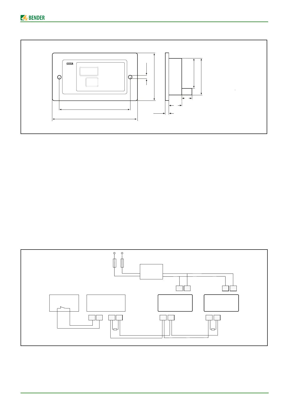
Dimension diagram
Mounting
The alarm indicator and test combination is suitable for screw
mounting. Available options are:
● Flush mounting
Required accessories:
a flush mounting box (supplied with the device)
● Wall mounting and cable-duct mounting
Required accessories:
a flush-mounting box (supplied with the device)
and a fixing set (to be ordered under No. B923711).
● Panel mounting type:
Required accessories:
a flush-mounting box (supplied with the device)
and a fixing set (to be ordered under No. B923780).
Dimensions of the switchboard cutout:160 x 75 mm.
Wiring diagram
* 107TD47 only: Optionally additional insulation monitoring
device for operating theatre lamp circuits
** Isometer = 107TD47 or isoMED427P
Maßbild
Montage
Die Melde- und Prüfkombination eignet sich für Schraubmonta-
ge in den Varianten:
● Unterputzmontage
Hierfür benötigen Sie die mitgelieferte Unterputzdose.
● Hohlwand- und Kabelkanal-Montage
Hierfür benötigen Sie die mitgelieferte Unterputzdose und
einen Befestigungssatz mit der Bestellnummer B923711
● Schalttafel-Montage
Hierfür benötigen Sie die mitgelieferte Unterputzdose und
einen Befestigungssatz mit der Bestellnummer B923780.
Die Schalttafelöffnung muss 160 x 75 mm betragen
Anschlussplan
* Nur 107TD47: Optionales zusätzliches Isolationsüberwachungs-
gerät für OP-Leuchtenkreise.
** Isometer = 107TD47 oder isoMED427P
MK2007CBM
145
170 mm
85
2,5 ... 5
15
5 mm
17
67
57
AB
120 Ω
BMS-Bus
max. 1200 m
ABAB
120 Ω
U2
V2
U2
V2
MK2007CBMIsometer
**
MK2007CBM
Us = 230 V
AC 50 ... 60 Hz
2 x 6 A
AN450
IN T1
OP *
*