7
MK2007CBM_D00218_01_M_DEEN/10.2015
MK2007CBM(T)
Commissioning
Connect the BMS bus to the supply voltage. Configurate the BMS
devices under consideration of the 10 Golden Rules for the de-
sign of BMS networks.
Once the supply voltage U
S
and the BMS bus is successfully con-
nected and after correct address assignment, the currently meas-
ured insulation resistance and the percentage indication of the
secondary load current appears on the seven-segment display.
Ordering details
Technical data
Insulation coordination in accordance with IEC 60664-1:
Rated insulation voltage ..................................................................................................... AC 250 V
Rated impulse withstand voltage/contamination level ....................................................... 4 kV/ 3
Voltage ranges
Supply voltage U
S
...........................................................................................................AC/DC 24 V
Frequency range U
S
....................................................................................................0, 50…60 Hz
Operating range U
S
..........................................................................................................12 … 28 V
Power consumption............................................................................................................ ≤ 2.5 W
Indicating and operating elementsfe
Display R, three-digit............................................................................... Insulation resistance in kΩ
Display range for isoMED427P..................................................................................... 10…999 kΩ
Display at R < 10 kΩ..........................................................................................0 (Insulation fault)
Display at R ≥ 999 kΩ................................................................................................................999
Display I, two-digit....................................................................................... Transformer load in %
LEDs...................................................................... ON, insulation fault, overload, over temperature
Buttons................................................................................................... Isometer test, buzzer mute
Buzzer alarm............................................................................................with buzzer mute function
Buzzer repeat factor .......................................................................................................... adjustable
Interface
Interface/Protocol............................................................................................................RS485/BMS
Baud rate .............................................................................................................................9.6 kBit/s
Cable length...................................................................................................................... ≤ 1200 m
Observe the factory setting of the parameters, in
particular the BMS address settings for the alarm
indicator and test combination and the insulation
monitoring device as well as the „Ten golden
rules“ on page 6 for designing a BMS network.
Check the function of the alarm indicator by start-
ing the self test of the MK2007CBM(T).
Type Designation Art. No.
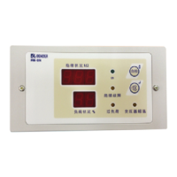
MK2007CBM
Alarm indicator and test
combination
(front foil with symbols)
B923813
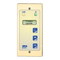
MK2007CBMT
Alarm indicator and test
combination
(front foil with text)
B923801
MK accessory Flush-mounting enclosure B923710
MK accessory Panel mounting kit B923780
MK accessory Dry wall installation kit B923711
Inbetriebnahme
Schließen Sie den BMS-Bus an und konfigurieren Sie die BMS-Ge-
räte unter Beachtung der 10 Goldenen Regeln für den Anschluss
von BMS-Netzwerken.
Nach korrektem Anschluss der Speisespannung U
S
und des BMS-
Busses sowie korrekter Adressierung erscheint auf den Sieben-
segment-Anzeigen der aktuell gemessene Isolationswiderstand
und die prozentuale Angabe des sekundären Laststroms.
Bestellangaben
Technische Daten
Isolationskoordination nach IEC 60664-1:
Bemessungsspannung ...................................................................................................... AC 250 V
Bemessungsstoßspannung/Verschmutzungsgrad .............................................................. 4 kV/3
Spannungsbereiche
Versorgungsspannung U
S
.............................................................................................. AC/DC 24 V
Frequenzbereich von U
S
............................................................................................. 0, 50…60 Hz
Arbeitsbereich von U
S
..................................................................................................... 12 … 28 V
Eigenverbrauch ................................................................................................................... ≤ 2,5 W
Anzeige- und Bedienelemente
Display R, dreistellig ............................................................................... Isolationswiderstand in kΩ
Anzeigebereich für isoMED427P.................................................................................. 10…999 kΩ
Anzeige bei R < 10 kΩ.....................................................................................0 ( Isolationsfehler)
Anzeige bei R ≥ 999 kΩ.............................................................................................................999
Display I, zweistellig ........................................................................ Transformator-Laststrom in %
LEDs........................................................................ ON, Isolationsfehler, Überlast, Übertemperatur
Tasten............................................................................... Isometertest, Summer-Stummschaltung
Summermeldung ....................................................................... quittierbar, mit Neuwertverhalten
Summerwiederholung ......................................................................................................einstellbar
Schnittstellen
Schnittstelle/Protokoll.................................................................................................... RS485/BMS
Baud Rate ........................................................................................................................... 9,6 kBit/s
Leitungslänge .................................................................................................................. ≤ 1200 m
Beachten Sie die Werkseinstellung der Parameter,
insbesondere die Einstellung der BMS-Adressen
für die Melde- und Prüfkombination und das Iso-
lationsüberwachungsgerät und die „10 Goldenen
Regeln“ auf Seite 6 zum Aufbau von BMS-Netz-
werken.
Führen Sie einen Funktionstest der Meldekombi-
nation durch. Starten Sie dazu den Selbsttest der
MK2007CBM(T).
Typ Bezeichnung Art.Nr.
MK2007CBM
Melde- und Prüf-
kombination
(Frontfolie mit Symbolen)
B923813
MK2007CBMT
Melde- und Prüf-
kombination
(Frontfolie mit Text)
B923801
MK-Zubehör Unterputzgehäuse B923710
MK-Zubehör Schalttafeleinbausatz B923780
MK-Zubehör Hohlwandeinbausatz B923711

 Loading...


