6
NGRM700_D00292_00_Q_XXEN/09.2017
Initial commissioning
1. Selecting language
2. HRG system (menu 6.1)
System voltage U
sys
phase-phase (menu 6.1)
for U
sys
≤ 4,3 kV: CD690, CD1000, CD4200, CD5000 (20 k)
for U
sys
> 4,3 kV: CD14400 (100 k)
Conversion ratio of the used potential transformers (U
NGR nom
) if available
Current through the NGR (I
NGR nom
)
Conversion ratio of the used measuring current transformer
Resistance R
NGR nom
3. Setting response values (menu 6.5)
Shutdown threshold value for voltage (
U
NGR
)
Shutdown threshold value for current (
I
NGR
)
Shutdown threshold values for resistance (
R
NGR
)
4. System settings of the relays (menu 6.6)
The factory setting for the relays is N/C operation. In case of a self test, the relays switch.
5. Field calibration (menu 6.7)
After the parameters have been entered, a field calibration can be carried out to set R
NGR
= R
NGR nom
.
Mute buzzer:
Low shutdown threshold values: may lead to false tripping.
High shutdown threshold values: the device may not trip at all.
N/C operation: Relay is energised during normal operation and is deactivated in the
event of a fault ("fail-safe")
N/O operation: Relay is de-energised in normal operation and is activated in the event of
a fault ("not fail-safe")
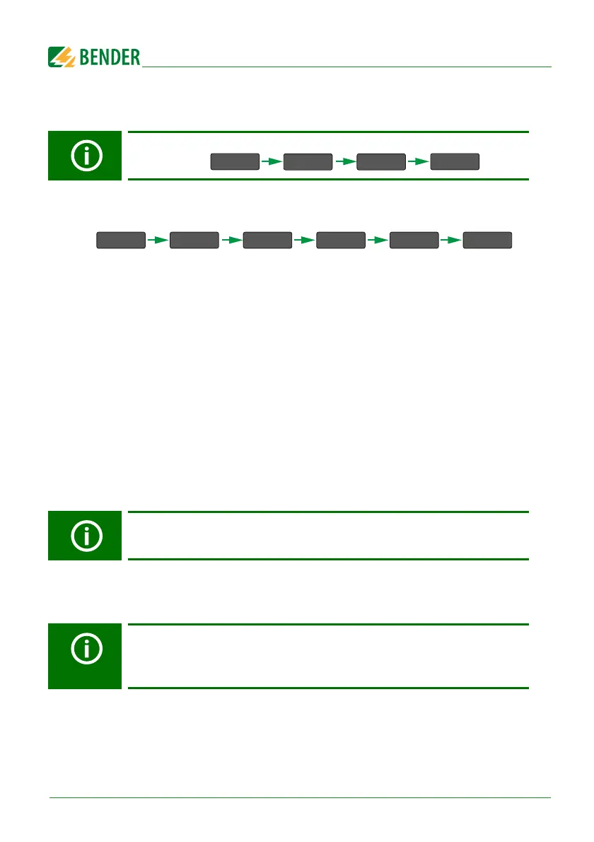
MENU OK
>
6 x
OK
7. … 7.1 …
>
>
OK
Display: 1. …

 Loading...


