Operation and settings
40
VMD460-NA_D00001_05_M_XXEN/01.2020
5. Operation and settings
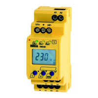
5.1 User interface
Legend
No. Element Function
1
ON
Power On LED, green;
lights when the voltage supply is available and the device is in operation;
flashes when the device is being started or when an internal device error has occurred
2
ALARM1
ALARM2
System disconnected:
Both LEDs light(yellow) in the case of a limit value violation of voltage or frequency, remote disconnec-
tion (remote trip, optional), df/dt (optional), vector shift detection (optional), unbalance (optional);
Both LEDs flash (yellow) in the case of an internal device error or fault in the contact monitoring
Only ALARM 1 lights: Reconnection conditions met. t
(ON)
elapses
3
Backlit LC display
4
INFO
ESC
Standard display: Standard display and device information
Menu display: Exit the parameter setting menu
without saving; go to the next higher menu level
5
TEST
Standard display: Pressing the TEST button (> 1.5 s) starts a manual self test which triggers both
alarm relays (tripping test to check the interface switches). In addition, the disconnection times are doc-
umented. Refer to "Manual self test" on page 74.
Menu display: Arrow-up button for parameter change and scrolling
6
RESET
Standard display: (> 1.5 s) Acknowledge fault messages from contact monitoring
Menu display: Arrow-down button for parameter change and scrolling
7
MENU
Standard display: Toggle between standard, menu and alarm display
Menu display: button
Jump to setting parameter; save changes
VMD460
LINETRAXX®
V