M A I N T E N A N C E P R A C T I C E S
(6) Troubleshooting Marginal Performance
In most cases the troubleshooting chart, Table 102, will localize afailure to the point where
simple voltage and resistance measurements will enable the technician to locate the specific
malfunctioning component. In some cases, however, failure of the equipment will be evidenced
by marginal performance. For instance, it will take bearings, but slowly. The indicator pointer
may hunt excessively, or the sensitivity or selectivity of the equipment may be inadequate. In
cases such as these proceed as follows :
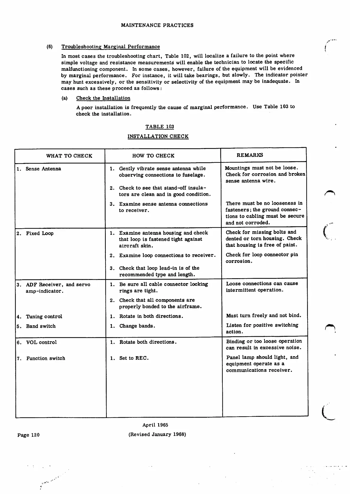
( a ) C h e c k t h e I n s t a l l a t i o n
Apoor installation is frequently the cause of marginal performance. Use Table 103 to
c h e c k t h e i n s t a l l a t i o n .
!
T A B L E 1 0 3
INSTALLATION CHECK
REMARKS
WHAT TO CHECK HOW TO CHECK
Mountings must not be loose.
C h e c k f o r c o r r o s i o n a n d b r o k e n
sense antenna wire.
Gently vibrate sense antenna while
observing connections to fuselage.
1. Sense Antenna
1.
C h e c k t o s e e t h a t s t a n d - o f f i n s u l a ¬
tors a r e c l e an and i n g o od con d i t i o n .
2.
T h e r e m u s t b e n o l o o s e n e s s i n
fasteners; the ground connec¬
tions to cabling must be secure
and not corroded.
3. Examine sense antenna connections
to receiver.
(
Check for missing bolts and
dented or torn housing. Check
that housing is free of paint.
C h e c k f o r l o o p c o n n e c t o r pi n
corrosion.
1. Examine antenna housing and check
tha t l o o p is f a s tene d t i ght a g a i nst
aircraft skin.
2 . E x a m i n e l o o p c o n n e c t i o n s t o r e c e i v e r.
2. Fixed Loop
3. C h e c k th a t lo o p l e a d- i n i s o f t h e
recommended type and length.
L o o s e c o n n e c t i o n s c a n c a u s e
intermittent operation.
1 . B e s u r e a l l c a b l e c o n n e c t o r l o c k i n g
rings are tight.
2 . C h e c k t h a t a l l c o m p o n e n t s a r e
p r o p e r l y b o n d e d t o t h e a i r f r a m e .
1. Rotate in both directions.
3. ADF Receiver, and servo
amp-indicator.
Must turn freely and not bind.
Listen for positive switching
action.
4. Tuning control
5. Band switch
1. Change bands.
Binding or too loose operation
can result in excessive noise.
Panel lamp should light, and
e q u i p m e n t o p e r a t e a s a
c o m m u n i c a t i o n s r e c e i v e r .
1. Rotate both directions.
6. VOL control
1. SettoREC.
7. Function switch
I
April 1965
(R e v i se d J a nu a r y 196 8 )
Page 120