2
OPERATION
The compressor is driven by the vehicle engine and is
operating continuously while the engine is running. Actual
compression of air is controlled by the compressor unload-
ing mechanism and the governor. The governor, which is
generally mounted on the compressor, maintains the brake
system air pressure to a preset maximum and minimum
pressure level.
INTAKE AND COMPRESSION OF AIR (LOADED)
During the down stroke of the piston, a slight vacuum is
created between the top of the piston and the cylinder head,
causing the inlet valve to move off its seat and open. (Note:
The discharge valve remains on its seat.) Atmospheric air
is drawn through the air strainer and the open inlet valve
into the cylinder (see Figure 4). As the piston begins its
upward stroke, the air that was drawn into the cylinder on
the down stroke is being compressed. Air pressure on the
inlet valve plus the force of the inlet spring, returns the
inlet valve to its seat and closes. The piston continues the
upward stroke and compressed air pushes the discharge
valve off its seat and air fl ows by the open discharge
valve, into the discharge line and to the reservoirs (see
Figure 5). As the piston reaches the top of its stroke and
starts down, the discharge valve spring and air pressure
in the discharge line returns the discharge valve to its
seat. This prevents the compressed air in the discharge
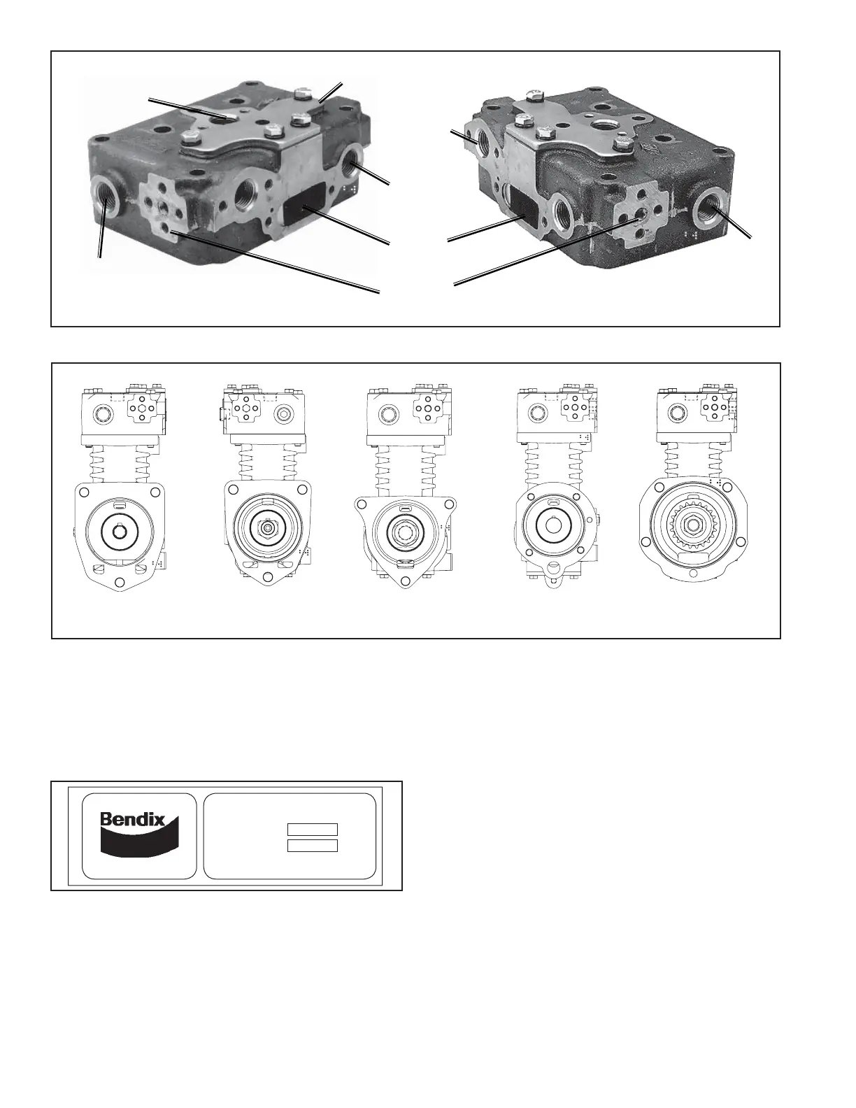
AIR INLET
WATER
UNLOADER COVER
PLATE
AIR DISCHARGE
WATER
AIR
DISCHARGE
GOVERNOR
MOUNTING
PAD
WATER
MANUFACTURED BY BENDIX
TU-FLO 750 COMPRESSOR
BENDIX NO.
SERIAL NO.
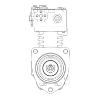
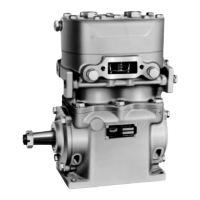
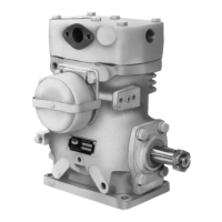
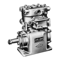
FIGURE 2 - MOUNTING CONFIGURATIONS
Various mounting and drive confi gurations, as shown in
Figure 2, are supplied as required by the vehicle engine
designs. A nameplate identifying the compressor piece
number and serial number is attached to the side of the
crankcase. (Reference Figure 3.)
FIGURE 3 - NAMEPLATE
FIGURE 1 - CYLINDER HEAD
CAT MACK
(MACK STYLE)
DETROIT
DIESEL
MACK
"FOXHEAD"
CUMMINS
MACK
EXTENDED