5
COOLING
Air fl owing through the engine compartment from the
action of the engine’s fan and the movement of the vehicle
assists in cooling the compressor. Coolant fl owing from the
engine’s cooling system through connecting lines enters the
head and passes through internal passages in the cylinder
head and is returned to the engine. Proper cooling is
important in maintaining discharge air temperatures below
the maximum recommended 400 degrees Fahrenheit.
Figure 8 illustrates the various approved coolant fl ow
connections. See the tabulated technical data in the back
of this manual for specifi c requirements.
AIR INDUCTION
There are three methods of providing clean air to the
Tu-Flo
®
750 compressor:
1. Naturally aspirated Local Air Strainer - Compressor
utilizes its own attached air strainer (polyurethane
sponge or pleated paper dry element).
2. Naturally aspirated Engine Air Cleaner - Compressor
inlet is connected to the engine air cleaner or the
vacuum side (engine air cleaner) of the supercharger or
turbocharger.
3. Pressurized induction - Compressor inlet is connected
to the pressure side of the supercharger or turbo-
charger.
See the tabulated technical data in the back of this manual
for specifi c requirements for numbers 2 and 3 above.
DISCHARGE LINE TEMPERATURE
When the temperature of the compressed air that enters
the air dryer is within the normal range, the air dryer can
remove most of the charging system oil. If the temperature
of the compressed air is above the normal range, oil as
oil-vapor is able to pass through the air dryer and into the
air system. Larger diameter discharge lines and/or longer
discharge line lengths can help reduce the temperature.
The air dryer contains a fi lter that collects oil droplets, and
a desiccant bed that removes almost all of the remaining
water vapor. The compressed air is then passed to the air
brake service (supply) reservoir. The oil droplets and the
water collected are automatically purged when the governor
reaches its "cut-out" setting.
For vehicles with accessories that are sensitive to small
amounts of oil, we recommend installation of a Bendix
®
PuraGuard
®
QC
™
oil coalescing fi lter, designed to minimize
the amount of oil present.
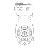
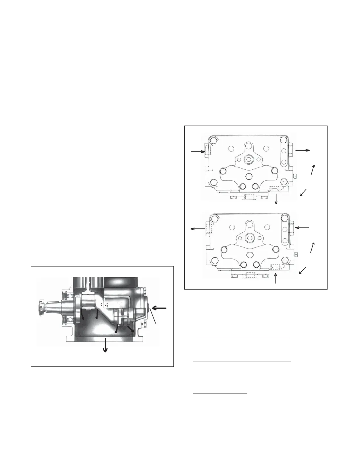
LUBRICATION
The vehicle's engine provides a continuous supply of oil
to the compressor. Oil is routed from the engine to the
compressor oil inlet. An oil passage in the compressor
crankshaft allows oil to lubricate the connecting rod crank-
shaft bearings. Connecting rod wrist pin bushings and
crankshaft ball bearings are spray lubricated. An oil return
line connected from the compressor drain outlet to the
vehicle engine crankcase allows for oil return. On fl ange
mounted models, the oil drains back directly to the engine
through the mounting fl ange.
FIGURE 7 - LUBRICATION (BASE MOUNT MODEL SHOWN)
OIL
INLET
OIL
OUTLET
WATER
IN
OR
(1 PORT
ONLY)
WATER
OUT
OR
(1 PORT
ONLY)
WATER OUT
WATER
OUT
WATER
IN
WATER
IN
FIGURE 8 - COOLING