Autostacker™ Parking Lift 55 P/N 5900002 — Rev. D — August 2019
In addition, for
each
Lift in your setup, you need from the Control Kit:
• Two Short Hydraulic Hoses (15 inches). One end connects to a Hydraulic Cylinder and the
other end connects to the Solenoid Valve Block. One per Hydraulic Cylinder.
• Two Long Hydraulic Hoses (105 or 108 inches). One Hose goes to the Hydraulic Cylinder
furthest from the MPU (on each Lift) and the other Long Hose connects to the next Lift.
• Two Solenoid Valve Blocks. One end connects to a Short Hydraulic Hose and the other end
attaches to a Tee Fitting. One per Hydraulic Cylinder.
• Two Hydraulic Elbow Fittings (JIC x ORB). Goes on the lower port on the Solenoid Valve
Block, and connects to the Short Hydraulic Hose. One per Solenoid Valve Block.
• Two Hydraulic Straight Fittings (NPT x ORB). One end attaches to the Solenoid Valve Block,
and the other end attaches to a Tee Fitting. One per Solenoid Valve Block.
To install the Hydraulic Lines:
1. Install a Velocity Fuse in the connectors near the bottom of each Hydraulic Cylinder.
Finger tighten those connections
Refer to About Velocity Fuses for more information.
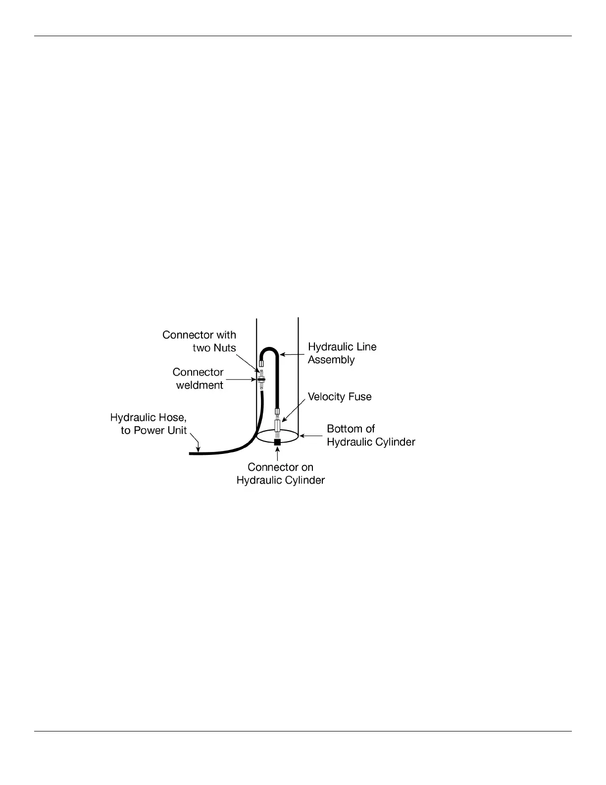
The following drawing shows a close-up of the connections to make to the Hydraulic Cylinders.
2. On each Cylinder, remove one Nut from the Connector with two Nuts, put the Connector with two
Nuts into the Connector Weldment, put the Nut you just removed back onto the Connector with
the two Nuts, and finger tighten both Nuts around the Connector Weldment.
3. On each Hydraulic Cylinder, connect the Hydraulic Line Assembly to the top end of the Connector
with the two Nuts and the other end to the top end of the Velocity Fuse
Finger tighten all the connections.
4. Find the necessary components for preparing the Solenoid Valve Blocks.
5. Prepare two Solenoid Valve Blocks, with an Elbow Fitting and a Straight Fitting in their required
locations, as shown in the previous drawing.
6. Attach a Tee Fitting to each Straight Fitting.
7. Secure the Solenoids Valve Blocks to the Lift Baseplates using the appropriate Bolts (2), Nuts (2),
and Washers (2) per Solenoid Valve.
Use size M6 x 1.0 x 55 Bolts.