1818
STEP 4
(Site Layout)
1. Determine which side of the lift will be the approach side.
2. Now determine where the power unit will be located.
The POWER SIDE column has the power unit mounting
bracket attached to the side.
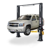
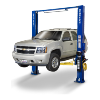
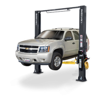
3. Use charts on pages12 and 13 to determine which lift
width layout you would like to use. Also, you can see image
above for reference.
4. Once a location is determined, use a carpenters chalk
line to layout an alignment line for the post locations. Keep
all dimensions square within 1/8” (3mm) or malfunctioning of
the lift can occur. (See Fig 4.1)
5. After the post locations are properly marked, use chalk
or crayon to make an outline of the posts on the floor at each
post location using the post base plates as a template.
6. CHECK ALL DIMENSIONS TWICE and make sure that
the layout is perfectly square.
STEP 5
(Installing the POWER SIDE post)
1. Before proceeding, double check measurements and
make certain that the base plate of each post are aligned
with the chalk line.
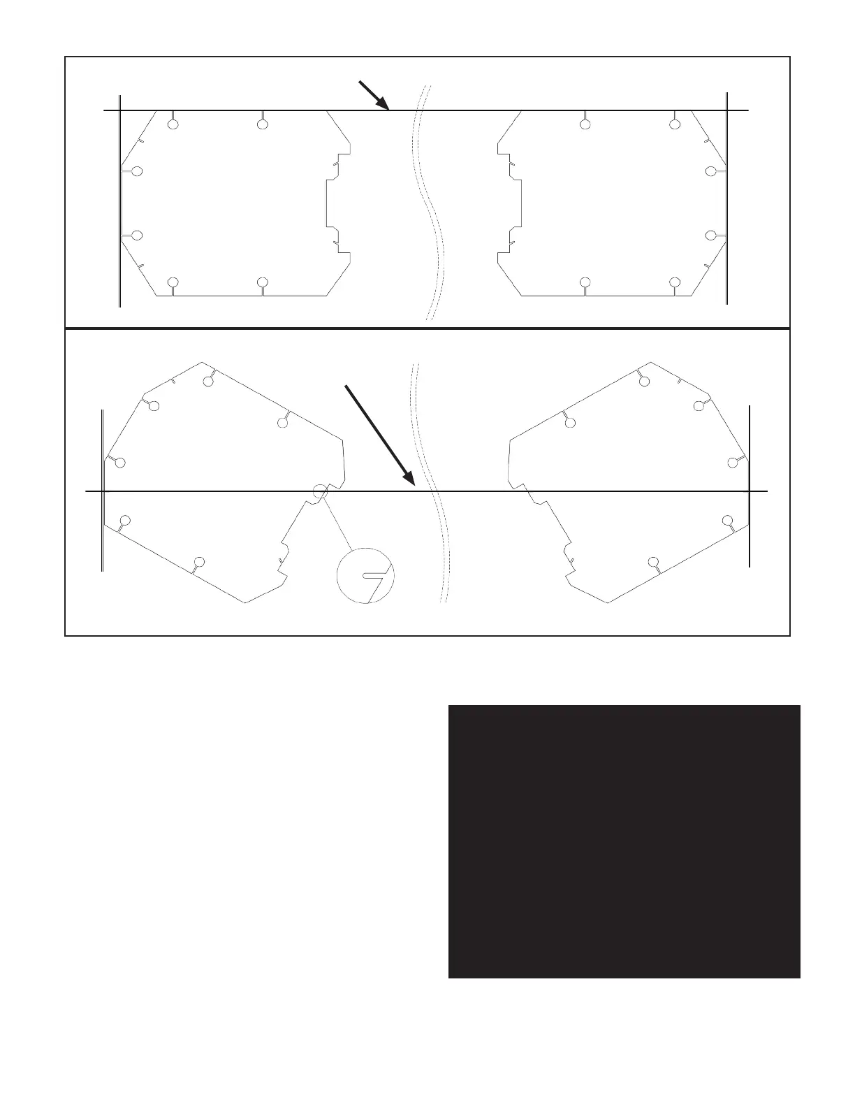
Fig 4.1
CHALK LINE
CHALK LINE
FOR XPR-10A CONFIGURATIONS USE NOTCHES TO ALIGN POSTS
FOR XPR-10 CONFIGURATIONS USE BASE PLATE EDGES TO ALIGN POSTS
OUTSIDE
BASEPLATE
OUTSIDE
BASEPLATE
OUTSIDE
BASEPLATE
OUTSIDE
BASEPLATE
NOTE:
OUR BENDPAK LIFTS ARE SUPPLIED WITH
INSTALLATION INSTRUCTIONS AND CONCRETE
FASTENERS MEETING THE CRITERIA AS
PRESCRIBED BY THE AMERICAN NATIONAL
STANDARD "AUTOMOTIVE LIFTS - SAFETY
REQUIREMENTS FOR CONSTRUCTION,
TESTING, AND VALIDATION" ANSI/ALI ALCTV-2011.
LIFT BUYERS ARE RESPONSIBLE FOR ANY
SPECIAL REGIONAL STRUCTURAL AND/OR
SEISMIC ANCHORING REQUIREMENTS
SPECIFIED BY ANY OTHER AGENCIES AND/OR
CODES SUCH AS THE UNIFORM BUILDING
CODE (UBC) AND/OR INTERNATIONAL
BUILDING CODE (IBC).
 Loading...