23
23
STEP 10
(Installing Hydraulic Lines)
Refer to illustration on Page 17.
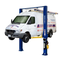
1. Install the bulkhead tee fitting into the Power Side
post. The through hole is located approximately 90 inches
from the floor on the back wall of the Power Side post.
2. Connect the Power Side cylinder hose to the tee fit-
ting. Be sure to route the hose through the retainer clips
inside the posts.
3. Route the Off Side cylinder hose (Crossover Hose)
up through the post and across the Overhead Assembly,
down the post and connect it to the bulkhead tee fitting.
(See Fig 10.1 and Fig 10.2)
STEP 11
(Routing the Equalizer Cables)
Refer to illustration on Page 16.
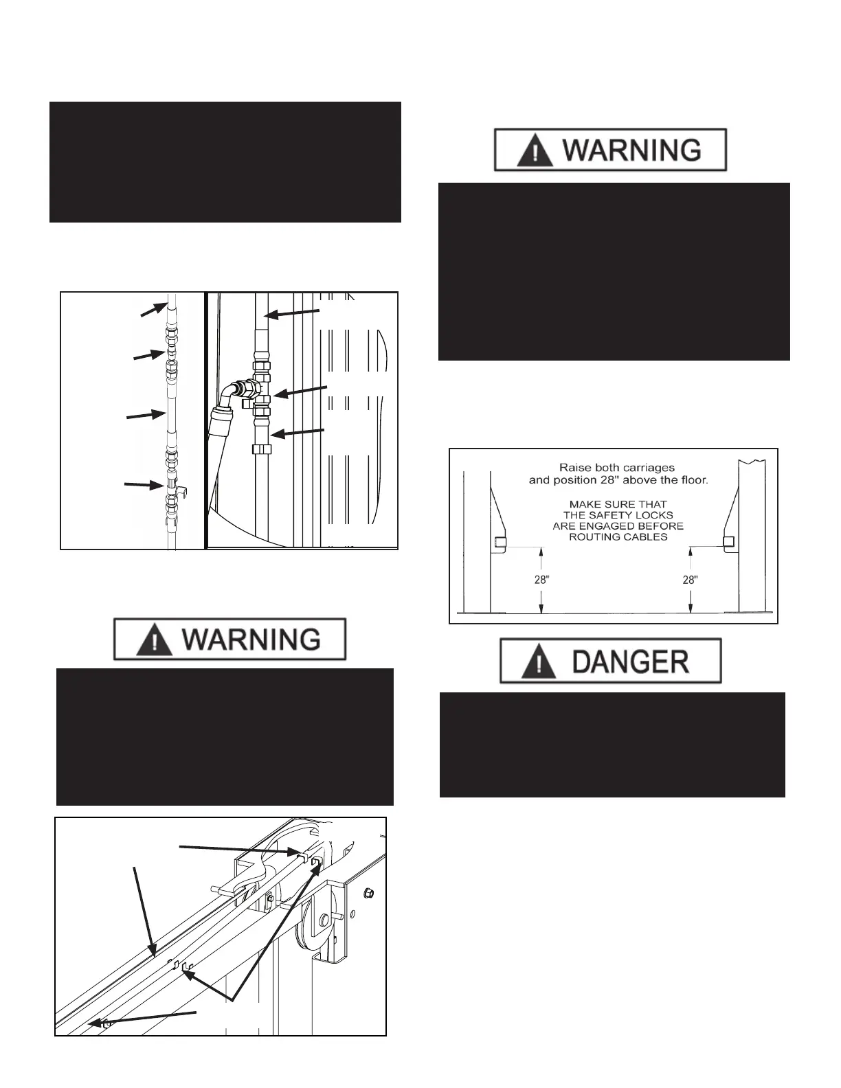
1. Raise and lock each Carriage approximately 28”
above the ground. (See Fig. 11.1)
2. With the Carriages locked at 28” off the floor, route the
Equalizer Cables up to the Top Trough.
3. Route the cables through the sheave brackets and
reinstall the sheaves. (See Fig. 11.2)
Note: The sheaves should have been removed in Step 6.
4. Insert the threaded end of the cable through the hole
on top of the carriage. Place M18 washer and M18 Nylock
nut on threaded cable end. Tighten cable nuts until taut,
Fig 10.1 B
Power
Side
Hose
Bulkhead
Fitting
Bulkhead
Fitting
Crossover
Hose
Crossover
Hose
WHEN ROUTING THE HYDRAULIC HOSE
THROUGH THE POSTS, MAKE SURE TO ROUTE
THROUGH THE HOSE CLIPS WELDED INSIDE
EACH POST. MAKE SURE THAT THE HOSE IS
CLEAR OF ANY MOVING PARTS. IT MAY BE
NECESSARY TO TIE THE HOSE CLEAR BY USING
NYLON TIE STRAPS OR WIRE.
Fig 10.2
Route Crossover
Hose through hose
clips
Microswitch
wire clips
WHEN THE CABLE ADJUSTING NUTS BOTTOM
OUT ON THE THREADED END OF THE CABLE
CONNECTOR AND THERE IS STILL SLACK IN THE
CABLES, THE CABLES HAVE STRETCHED
BEYOND THE SAFE USEFUL LENGTH AND NEED
TO BE REPLACED WITH FACTORY APPROVED
CABLE ASSEMBLIES. DO NOT PLACE WASHERS,
SPACERS OR OTHER DEVICES TO “SHORTEN”
THE EFFECTIVE CABLE LENGTH AS DAMAGE TO
THE LIFT OR INJURY TO PERSONS MAY OCCUR.
Fig 11.1
MAKE SURE THAT THE SAFETY LOCKS ON EACH
POST ARE FULLY ENGAGED BEFORE
ATTEMPTING TO ROUTE EQUALIZER CABLES AND/
OR HOSES. CARRIAGES MUST BE EQUAL HEIGHT
FROM THE FLOOR BEFORE PROCEEDING.
FOR WIDE CONFIGURATION, A 13” EXTENSION
FOR SYMMETRIC MODELS OR AN 8” EXTENSION
FOR ASYMETRIC, MUST BE INSTALLED TO THE
CROSSOVER HOSE. A JIC TO JIC STRAIGHT
FITTING HAS BEEN PROVIDED TO CONNECT THE
CROSSOVER HOSE TO THE EXTENSION HOSE IN
THE PARTS BOX. (See Fig. 10.1 A)
Fig 10.1 A
Extension
Hose
Extension
Hose Fitting
 Loading...