Section 4 — Wiring the Hardware
17
11
1087
912
1413
20 to 35 Vdc
6
5
4
3
21
2
3
4
5
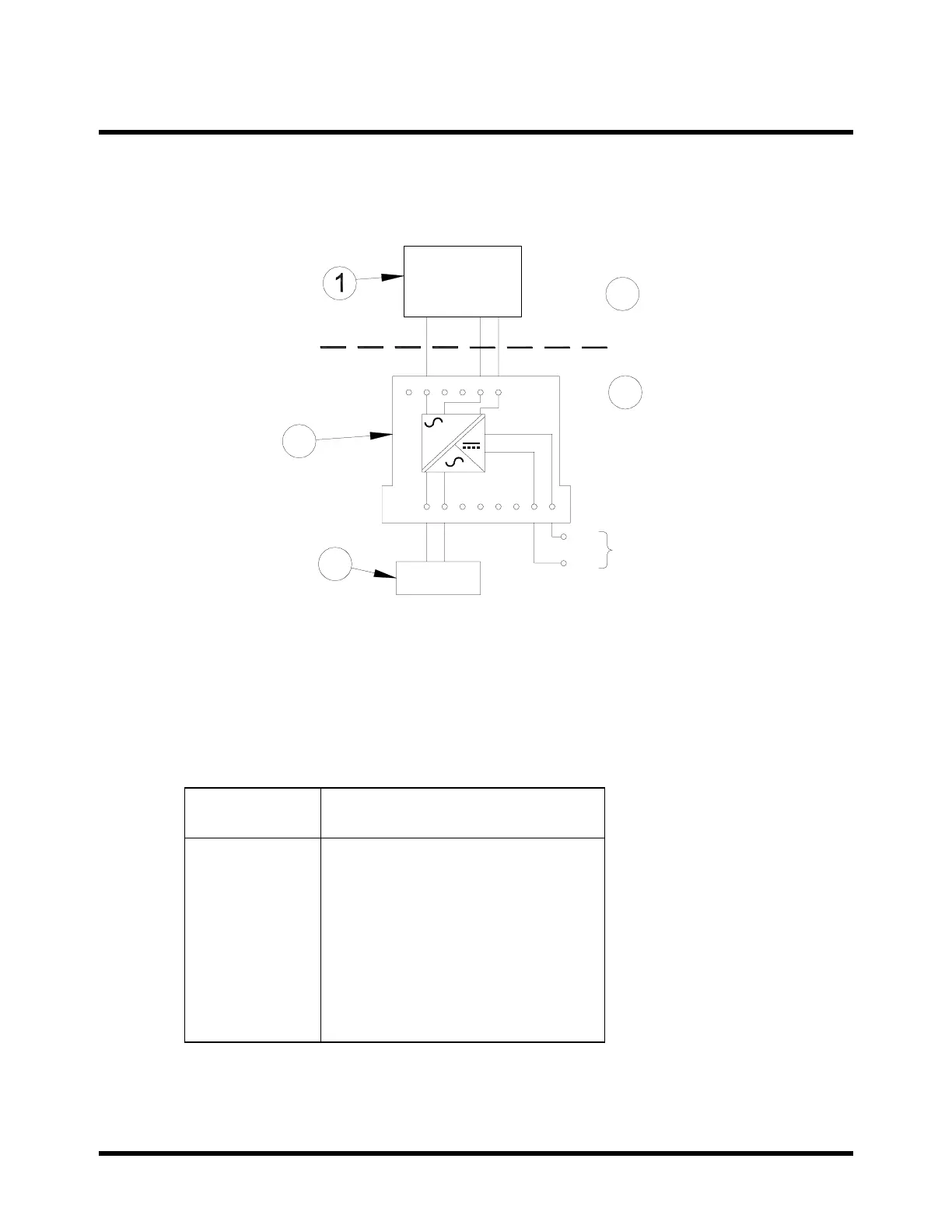
4.1 Location of Terminals on the Vibration
Transducer Interface Module
1) Transducer
2) Hazardous Area
3) Safe Area
4) Vibration Transducer Interface
5) 3500 Monitor
Terminal
Number
Function
2
5
6
7
8
13
14
Supply to hazardous area
Signal input
Transducer Common
Monitor Common
Isolator Signal Output
Power Supply Common
Power Supply Positive (+Vs)
Notice that the module terminal connections are located at the following positions:


 To Next Page