Section 5 — Maintenance and Troubleshooting
31
• Replace the hazardous-area connector.
5.2.1 Bench Testing Isolators
Test potentially faulty modules in workshop conditions using the installation
instructions in "Installing the Hardware". Test the suspected module using the
following procedure:
1. Connect a power supply to a spare backplane.
2. Plug the suspect module into any position on the backplane.
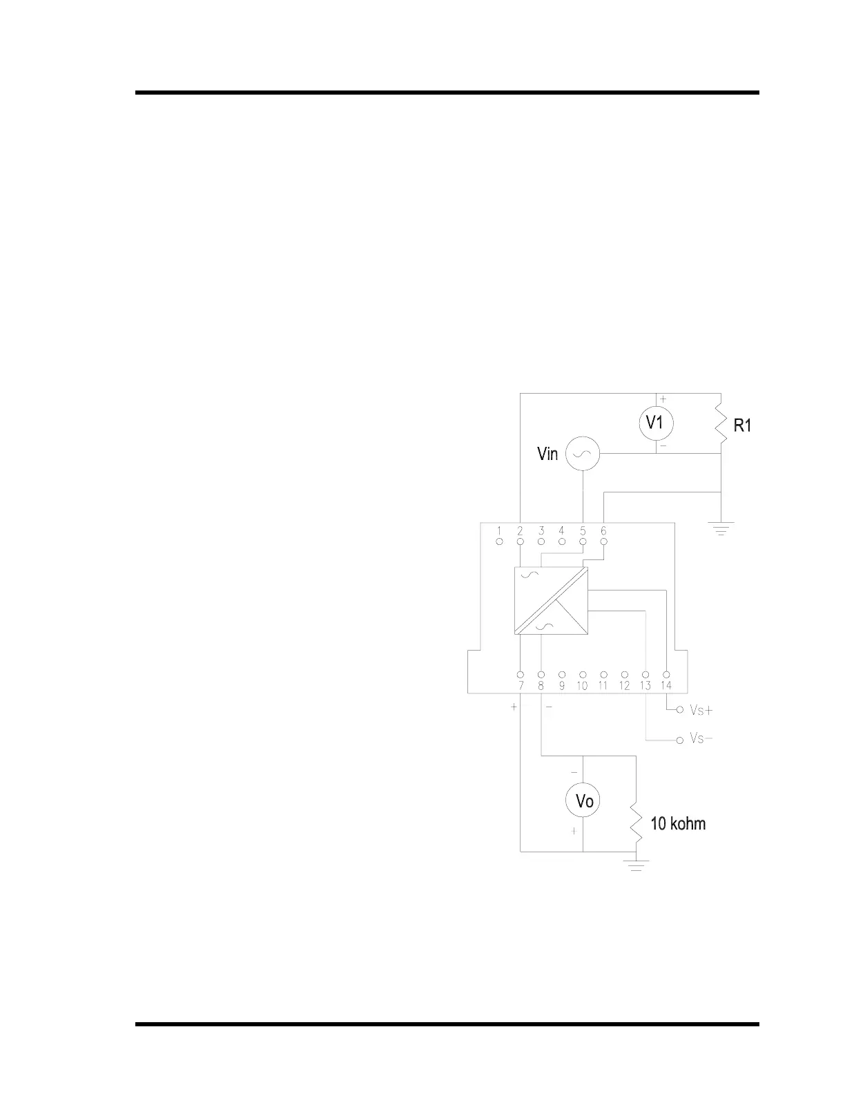
3. Wire the module as shown.
R1 = 1000 Ω
V1 = Digital Voltage
Meter
Vin = Function
Generator
Vo = Digital Voltage
Meter
Vs + = +20 to +35 Vdc
Vs - = Common
4. Set the input to the module to
the following:
Vin = 0.707 Vrms @
100 Hz
-6.0 Vdc offset
5. Verify that the output is as
follows:
V1 ! -19.0 Vdc
Vo = 0.707!0.035 Vrms
@ 100 Hz -5.9 to -6.1 Vdc