3500 Galvanic Isolator Interface Manual
18
32
1
7
6
4
5
8
2
3
4
5
6
7
• Terminals 1 through 6 are on the top of the Vibration Transducer Interface module.
These terminals connect to the screw clamp connector for the hazardous-area
connections.
• Terminals 7 through 14 are located on the bottom of the Vibration Transducer
Interface module and connect to the backplane. These pins are the safe area
connections.
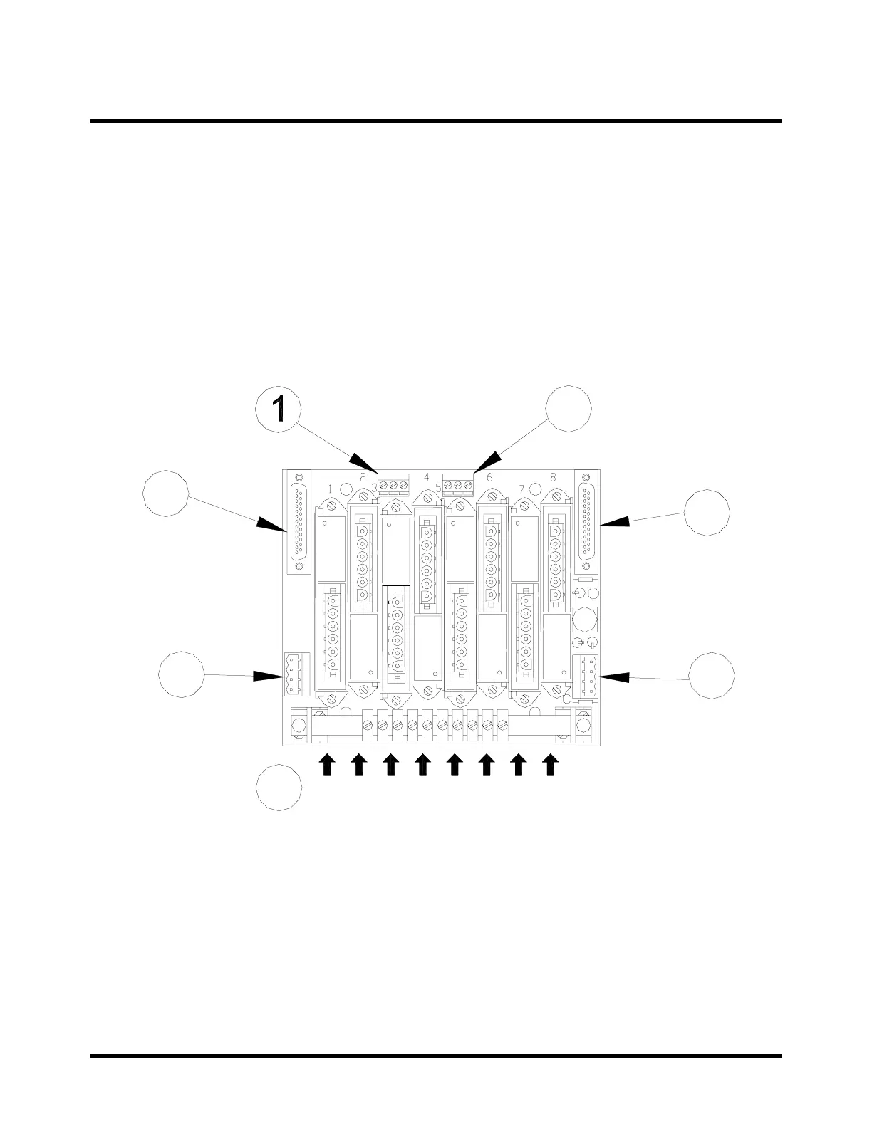
4.2 Location of Terminals on the Backplane
4.2.1 Vibration Backplane
1) OK Inhibit Contacts (external): Vibration Transducer Interfaces 1 to 4.
2) OK Inhibit Contacts (external): Vibration Transducer Interfaces 5 to 8.
3) Signal and Common: Terminals 7 & 8 of Vibration Transducer Interfaces 1 to
4.
4) Signal and Common: Terminals 7 & 8 of Vibration Transducer Interfaces 5 to
8.
5) Power Input/ Output: Input: Terminals 13 & 14 of all Vibration Transducer
Interfaces; Output: Bussed Power to Adjacent Backplanes.
6) Power Input/ Output: Input: Terminals 13 & 14 of all Vibration Transducer
Interfaces; Output: Bussed Power to Adjacent Backplanes.
7) Position of Vibration Transducer Interfaces 1 to 8 (Position 1 = Ch1.).