Section 3 — Installing the Hardware
9
1
2
3
3
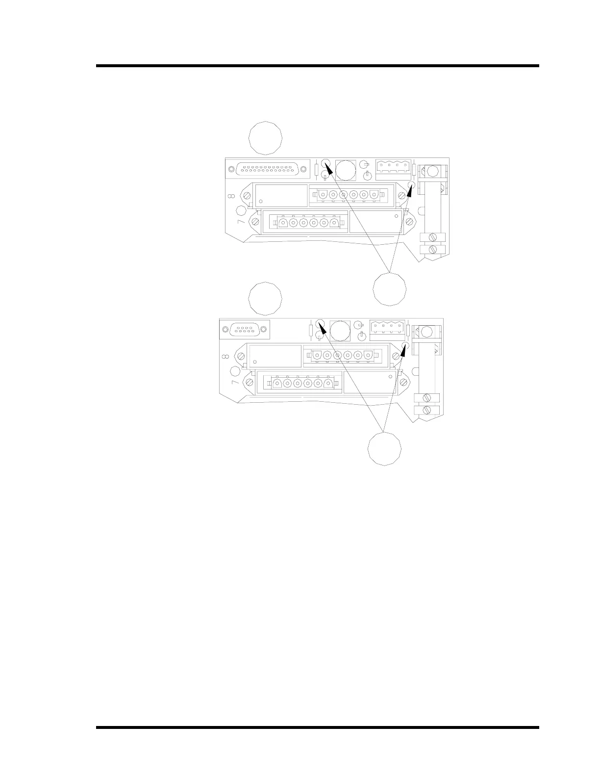
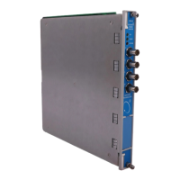
Verify that at least one power supply LED is on. One LED will be on for each
power supply that is installed.
1) Vibration Backplane
2) Keyphasor Backplane
3) Power Supply LEDs
3.2.4 Installing the Earth Rail
An earth rail provides a termination point for shield and spare wires. It also
provides a grounding location for transducers if local wiring codes require an
earth ground. Reference local wiring codes for any wiring restrictions.
The 3500 Galvanic Isolator Interface system does not require a high integrity
earth and the transducers can be left floating or be earthed at any one point.
Refer to the 3500 Field Wiring Package (130432-01). Do not wire transducer
common to earth. A "floating" system is recommended, except for the
Aeroderivative Interface Module (part number 86517) which requires a grounded
system for noise immunity.