3500 Galvanic Isolator Interface Manual
20
0V0V
V2
V1
V2
0V0V
V1
V2
0V
V1
0V
V2
0V0V
V1
4
1
2
3
4
3
5
5
5
5
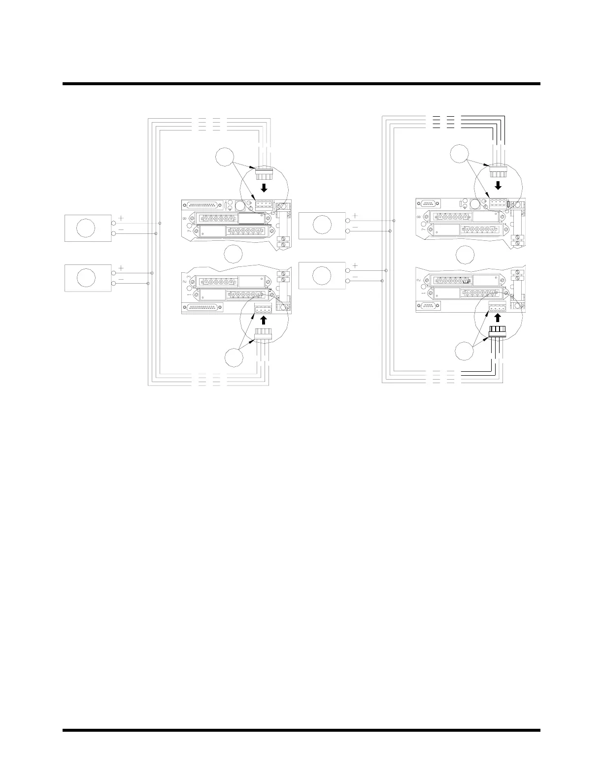
1) Vibration Backplane
2) Keyphasor Backplane
3) Connector Position “A”
4) Connector Position “B”
5) Power Supply
To reduce wiring while powering the 3500 Vibration Transducer Interface system, we
recommend using a "ring-main" system. A "ring-main" system has the following
characteristics and limitations:
1. An individual backplane can be removed from power without effecting the operation
of the other backplanes.
2. Power MUST connect to the next backplane as shown in the figure on the next
page.
3. The power supply current in the "ring-main" system must NOT exceed 3.8 amps
from a single power supply (Refer to the data sheet at the end of this manual).
4. Wire sizes must accommodate load and voltage drop.
 Loading...