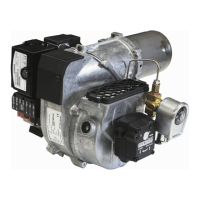
INSTRUCTIONS PUMP TYPE DANFOSS BFP41
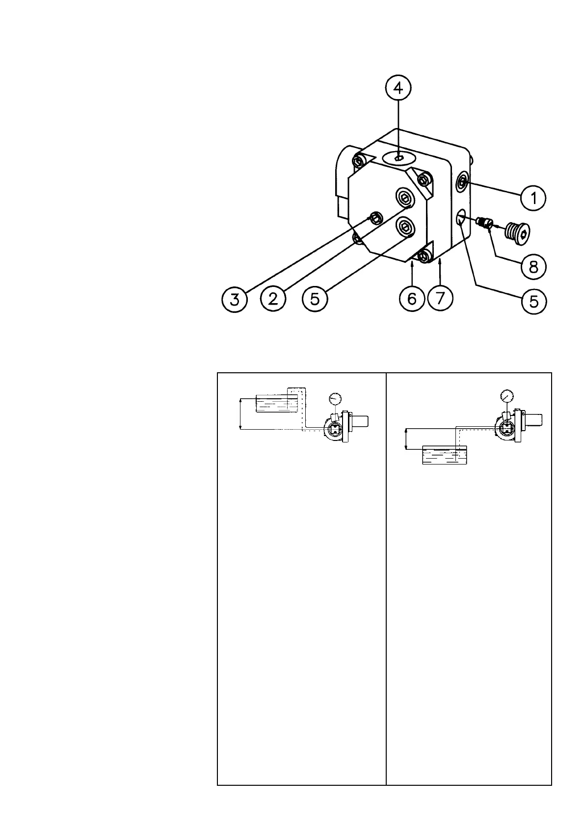
COMPONENTS
1.Nozzle port G 1/8"
2.Pressure gauge port
3.Pressure adjustment, 4mm allen key
4.Cartridge filter
5.Vacuum gauge port G 1/8"
6.Return line G 1/4"
7.Suction line G 1/4"
8.Return plug
TECHNICAL DATA
Viscosity range: 1,3-12,0 mm
2
/s
Pressure range: 7-15 bar
Oil temperature: -10 to +70°C
SUCTION LINE TABLES
The suction line tables consist of
theoretically calculated values where
the pipe dimensions and oil velocity
have been matched so that turbulences
will not occur. Such turbulences will
result in increased pressure losses and
in acoustic noise in the pipe system. In
addition to drawn copper piping a pipe
system usually comprises 4 elbows, a
non-return valve, a cut-off valve and
an external oil filter.
The sum of these individual resistances
is so insignificant that they can be
disregarded. The tables do not include
any lengths exceeding 100 m as
experience shows that longer lengths
are not needed.
The tables apply to a standard fuel oil
of normal commercial quality according
to current standards. On commissioning
with an empty tube system the oil
pump should not be run without oil for
more than 5 min. (a condition is that the
pump is being lubricated during
operation).
The tables state the total suction line
length in metres at a nozzle capacity of
2,5 kg/h. Max. permissible pressure at
the suction and pressure side is 2,0
bar.
PURGING
On 1-pipe systems it is necessary to
purge the pump. On 2-pipe systems
purging is automatic through the return
line.
Height Pipe diameter
H ø6 mm ø8 mm ø10 mm
mmmm
4,0 33 100 100
3,5 31 98 100
3,0 29 91 100
2,5 27 85 100
2,0 25 79 100
1,5 23 72 100
1,0 21 66 100
0,5 19 60 92
Two-pipe system
0 17 53 100
-0,5 15 47 100
-1,0 13 41 99
-1,5 11 34 84
-2,0 9 28 68
-2,5 7 22 53
-3,0 5 15 37
-3,5 3 9 22
4,0 1 3 6
Two-pipe system
Height Pipe diameter
H ø6 mm ø8 mm ø10 mm
mmmm
Height Pipe diameter
H ø4 mm ø5 mm ø6 mm
mmmm
Height Pipe diameter
H ø4 mm ø5 mm ø6 mm
mmmm
4,0 51 100 100
3,5 45 100 100
3,0 38 94 100
2,5 32 78 100
2,0 26 62 100
1,5 19 47 97
1,0 13 31 65
0,5 6 16 32
1-pipe system 1-pipe system
With an underlying tank a 1-pipe-
system is not recommended
171 505 07 96-01
H
H