ELECTRIC EQUIPMENT
OIL BURNER CONTROL: LOA21... / LOA24...
FUNCTION
1. Switch on operating switch and twin thermostat
The burner motor starts, an ignition spark is formed, the prepurge goes
on till the prepurge period expires and the solenoid valve opens (2).
2. Solenoid valve opens
Oil mist is formed and ignited. The photocell indicates a flame.
(1) The ignition spark goes out 15 s. after flame indication (LOA24.171...).
(2) The ignition spark goes out 2 s. after flame indication when the ignition
transformer is connected to terminal 7 (LOA24.173...).
3. The safety time expires
a. If no flame is established before this time limit the control cuts out.
b. If for some reasons the flame disappears after this time limit, the
burner will make an attempt to re-start.
3-4. Operating position
If the burner operation is interrupted by means of the main switch or the
thermostat, a new start takes place when the conditions in accordance
with point 1 are fulfilled.
The oil burner control cuts out
A red lamp in the control is lit. Press the reset button and the burner
re-starts.
Post-ignition
(2) If a post-igniton of 15 s. is wanted, move the ignition transformer from
terminal 7 to terminal 6 (LOA24.173...).
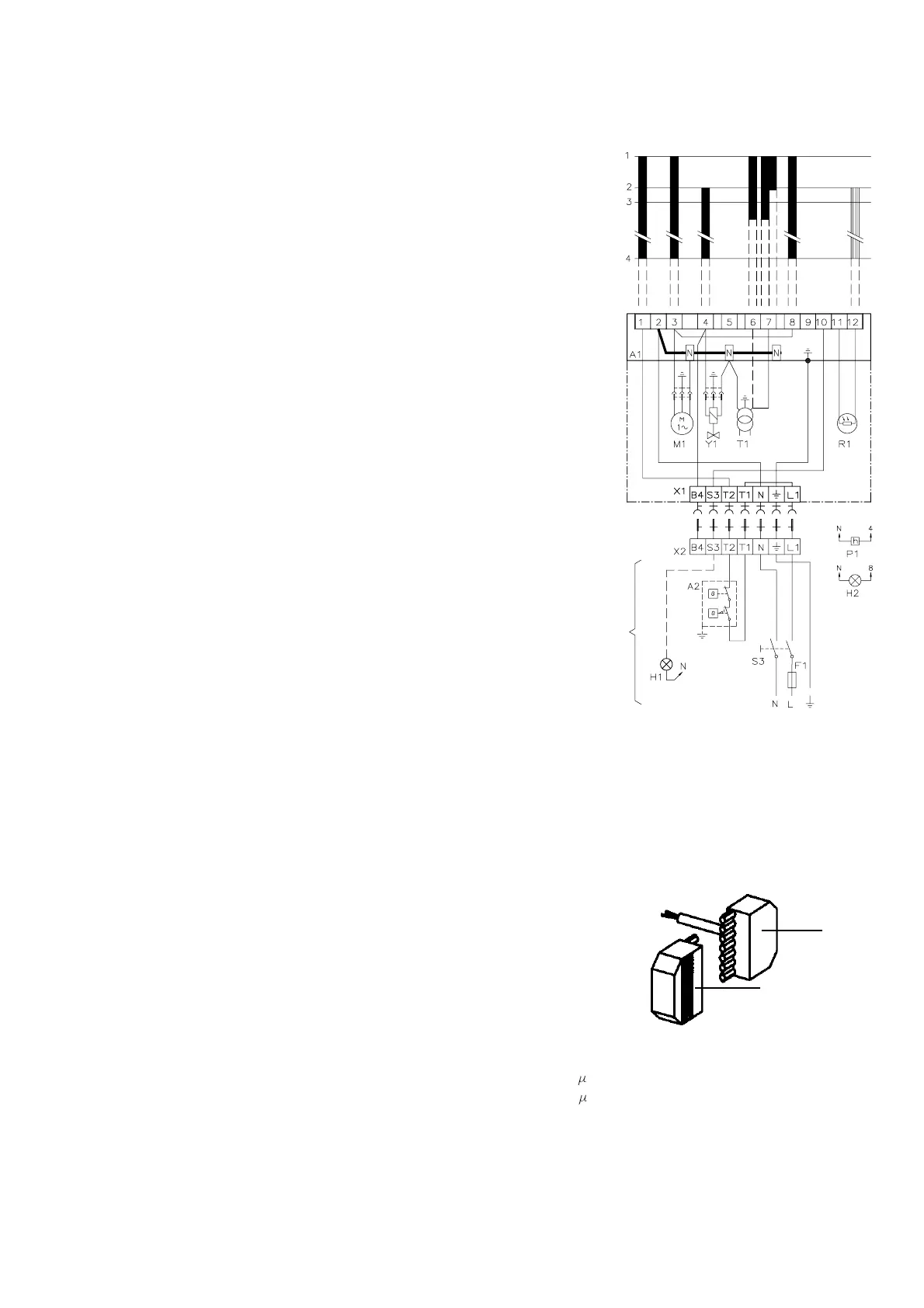
LIST OF COMPONENTS
A1 Oil burner control R1 Photoresistor
A2 Twin thermostat S3 Main switch
F1 Fuse, max. 10A T1 Ignition transformer
H1 Alarm lamp Y1 Solenoid valve
H2 Signal lamp (optional) X1 Plug-in contact, burner
M1 Burner motor X2 Plug-in contact, boiler
P1 Time meter (optional)
Mains connection and fuses in accordance with local regulations.
TECHNICAL DATA
Pre-ignition time: 13 s
Pre-purge time: 13 s
(1) Post-ignition time: 15 s
(2) Post-ignition time: 2 s
Safety lock-out time: 10 s
Reset time after lockout: » 50 s
Reaction time on flame failure: max. 1 s
Ambient temperature: from - 20 to +60°C
Min. current with flame established: 65 A
Max. photo current at start: 5 A
Enclosure: IP 40
(Under voltage proof only LOA24...)
CONTROL OF PHOTO CURRENT
Current through photo unit is measured with a d.c. ammeter (a moving coil
instrument connected in series with the photo unit).
WIRING DIAGRAM
* If there is no plug-in contact (X2) on the boiler,
connect to the contact enclosed. In case the
twin thermostat is in series on incoming phase
L1, a loop between the terminals T1 and T2 is
necessary.
OUTER ELECTRICAL CONNECTION
X1
X2
171 415 20 04-01
*
(1)(2)