X13 Exploded Views May 2007
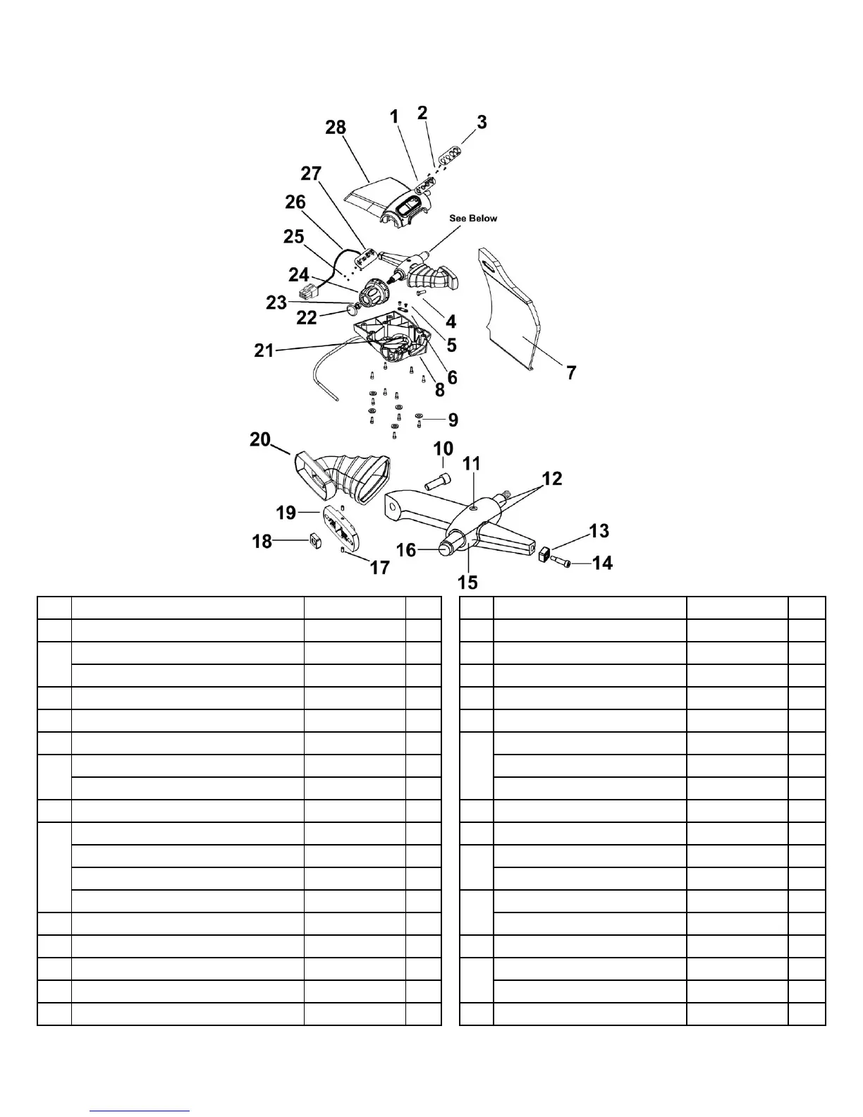
8) GAUGE PLATE ASSEMBLY
1 Upper Mount 3875-00237 15 Cam Assy (Items 11-16) 4375-00232
2 Screw 2175-00528 16 Cam (not sold separately)
Overlay, Manual 3175-00945 17 Screw 2175-00500
3
Overlay, Auto 3175-00941 A 18 Cylindrical Nut 3375-01276
4 Screw 2175-02756 19 Adjustment Block 3275-00219
5 Screw 2175-00517 20 Boot 3875-00236
6 Clamp 3375-01286 Cable 2375-00175
Gauge Plate 3775-00458 Grommet 2275-00609 E
7
Gauge Plate 3775-00501 JM
21
Stop Pin, Index Knob 3375-01393 E
8 Lower Housing 3875-00207 22 Cap 2275-00414
Screw (Upper/Lower Housing) 2175-02744 23 Nut 2175-00504
Screw, Short (Housing to Base) 2175-02744 Index Knob 3875-00173
Screw, Long (Housing to Base) 2175-02749
24
Index Knob 3875-00255 CB
9
Washer (Clam Shell to Base) 2275-00586 Nut 2175-00077
10 Screw 2175-02779
25
Lock washer 3275-00013
11 Dowel Pin 2275-00581 26 Upper Wire Harness 4175-00715
12 Flange Bushing 2275-00526 Upper PCB, Manual 2675-00921
13 Slider Arm 3875-00182
27
Upper PCB, Auto 2675-00918 A
14 Shoulder Bolt 2175-00501 28 Upper Housing 3875-00208
JM = Jersey Mike / CB = Cracker Barrel / A = X13A / E = X13E