If you cannot reach the correct closed position because you are
blocked by the mechanical stop, loosen the mechanical stop so that
you have enough space to go to the correct closed position, then
return to step 1.
5. Turn the setting screw of the gray cam corresponding to the
counterclockwise travel limit switch (2 in Figure 1) with a
screwdriver.
The cam disk is then turning.
6. Set the cam disk until you hear a click from the switch. It
indicates that the switch has been triggered.
Perform complete electrical valve opening and closing operations to
check that everything is correct. If it is not the case, return to step 1.
It is mandatory that the motor stops on the travel limit switch and
not on the mechanical stop (check available extra travel to the stop
with the handwheel).
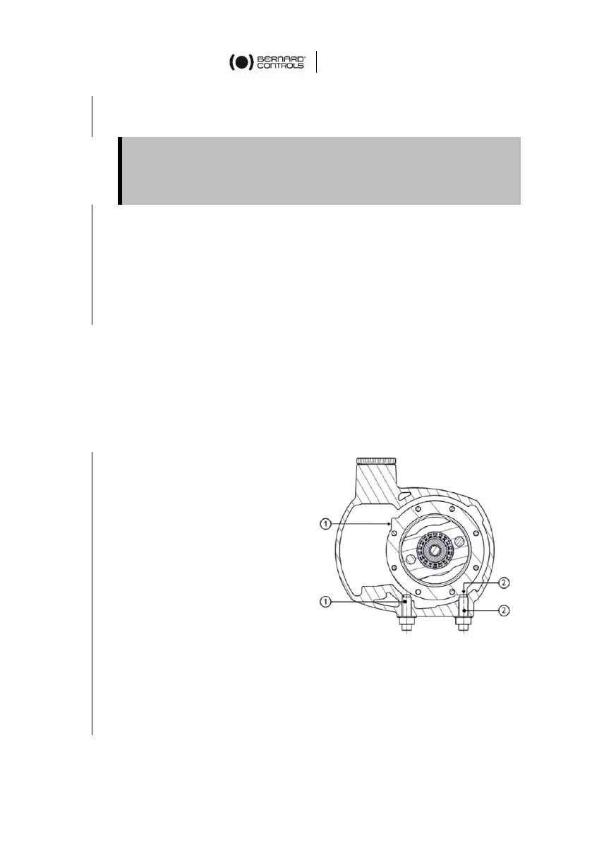
8.2 Calibration of mechanical stops
1. Loosen the nut
corresponding to the
clockwise mechanical stop
(2 in Figure 3).
2. Turn back the mechanical
stop 1.5 turns.
3. Drive the actuator to the
clockwise travel limit
position.
4. Get the mechanical stop in
contact with the output
sleeve then move it back
1.5 turns.
5. Tighten the nut to keep the mechanical stop in position.
6. Loosen the nut corresponding to the counterclockwise
mechanical stop (1 in Figure 3).
 Loading...