19
7. Perform steps 2 to 5 for the counterclockwise direction.
8.3 Calibration of cams corresponding to signaling
switches (if wired)
1. Slightly drive the output in the clockwise direction using the
manual override.
2. Set the blue cam corresponding to the clockwise signaling
switch (3 in Figure 1).
3. Slightly drive the output in the counterclockwise direction
using the manual override.
4. Set the Gray cam corresponding to the counterclockwise
signaling switch (4 in Figure 1).
8.4 Calibration of positioner (OPTION)
1. With a voltmeter, check
that the voltage at test
points 2-3 of the
potentiometer is equal to
0.6 V.
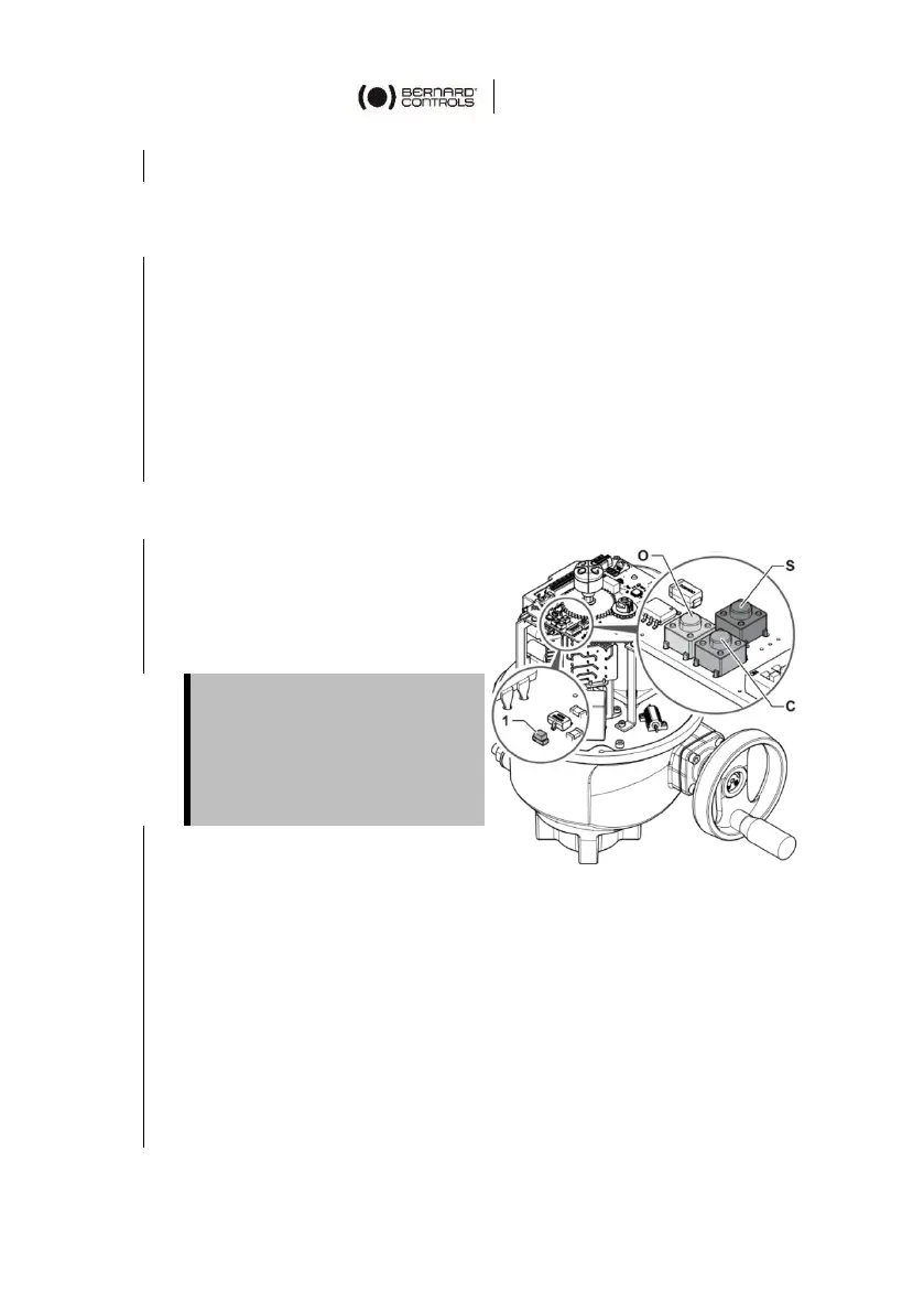
2. Press the S local setup
command (see Figure 4)
for 5 seconds to enter the
stroke calibration mode.
The LED (1) starts blinking.
3. Press the O local open command until the required open
position is reached.
4. Once the opening switch is tripped, press the S local setup
command to validate the position.
5. Press on the C local close command until the device closes
completely.
The voltage must never go
below 0.6 V. If it does, adjust
the potentiometer by turning
its shaft using a flat blade
screwdriver so that the voltage
reaches 0.6 V.
 Loading...