Do you have a question about the Bernard Controls AQ7L and is the answer not in the manual?
The AQL actuator is delivered in a cardboard box and should be stored under a shelter, in a clean and dry place.
Actuator features lifetime lubrication and requires no specific maintenance, but check for condensation in wet atmospheres.
Actuator is supplied with adapters to ensure the output fits your valve shaft. Insert the accurate square adapter.
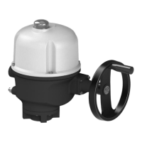
Change indicator orientation for counter-clockwise closing by turning the cap 90° for actuators configured to close clockwise.
Verify power supply voltage, connector tightness, valve position with manual override, and electrical operation direction and stops.
Cams rotate with the output shaft, triggering switches. Adjust cams by turning screws until a click is heard.
Actuator has 4 cams: 2 for travel limits (cut motor power) and 2 for signalling (indicate proximity to end position).
AQ7L has mechanical stops and cams. Adjustments involve stop screws and cams for both directions, with specific screw turn ratios.
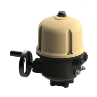
Board is factory pre-set. Setup is automatic. Press SW1 for 5 seconds to run setup, indicated by a blinking yellow LED.
Switch off power, check for valve or stop issues, fix the issue, then switch power on again and operate actuator.
Use SW2 dip switches with power off to set closing direction (SW1) and fallback position (SW2 & SW3).
| Brand | Bernard Controls |
|---|---|
| Model | AQ7L |
| Category | Switch |
| Language | English |